The Introduction Of SDN 3 Lukluk Environment Using Augmented Reality Application
on
p-ISSN: 2301-5373
e-ISSN: 2654-5101
Jurnal Elektronik Ilmu Komputer Udayana
Volume 9, No 2. November 2020
The Introduction of SDN 3 Lukluk Environment Using Augmented Reality Application
Ida Bhujangga Bagus Dili Putraa1, I Gede Arta Wibawaa2,
aInformatics Department, Udayana University
Jalan Raya Kampus Unud, Jimbaran, Bali, 80361, Indonesia 1bagus34ixk@gmail.com 2gede.arta@unud.ac.id
Abstract
Every year a lot of new students entering the school. To introduce new students to the school environment, the school holds an event to introduce the school environment to make them know their school environment better. However, there are still students who do not know their school environment very well. In the school environment there are many buildings with different names and to remember all of them correctly is not easy and takes a lot of time to look at all of them. To remember all the location of the buildings and its names, it would be better if there was an application that can visualize the buildings very well. Technologies that can provide visualization and is easy to use is Augmented Reality. Augmented Reality can display the whole school environment, making it easier to see all the buildings with their names in the school environment. AR can be easily used, user only need to install AR on their smartphone device. This AR application is marker-based so that user only need to scan the marker provided with the camera and the school environment and information can be displayed.
Keywords: Augmented Reality, Marker-based, Unity, Vuforia, School Environment
SDN 3 Lukluk is one of the primary schools in Badung regency, Mengwi. Every year an introduction to the school environment is held which serves to introduce the name and location of the school building to new students. Even though the introduction of this school has been carried out there are still students who do not know all the names and locations of the school environment correctly. This is because the introduction to school is usually explained verbally. This introduction to the school environment is better explained by providing visualization of the shape and location of the school environment because making visual explanations provides better benefits in understanding and learning something compared to verbally [1].
In previous research, there was a study regarding the introduction of the school environment using the AR application which provides information about the school building location and their names [6]. In the previous research, there are still deficiencies in the Augmented Reality because the form of information provided is in the form of images, therefore it is better to provide information about the school environment in 3D [6].
Augmented Reality can be used to give a visual explanation about the school environment and can display a 3D object. Marker-based Augmented Reality has the advantage of the ease of development and ease of use. With Augmented Reality, the student can see the school environment easier and can see all of the school environment which can save their time rather than seeing them one by one. Therefore, research will be carried out to develop an Augmented Reality application that can generate a marker-based 3D object of SDN 3 Lukluk environment.
Augmented Reality is a technology that combines two-dimensional or three-dimensional virtual objects into a three-dimensional real environment and then projects these virtual objects in real-
time. Unlike virtual reality, which completely replaces reality, augmented reality simply adds or complements reality [2].
Marker-based tracking is AR which uses two-dimensional object markers which has a pattern that will be read by the computer via webcam or camera media connected to a computer, usually a black and white illustration of a square with a border bold black and white background. Where these markers function to be read and recognized by the camera and the camera will render the object on top of the marker [4].
Unity 3D is a cross-platform based game engine that is used as an integrated tool for game creation, building architecture, and simulation. Unity can be used to create a game that can be used on computer devices, Android smartphones, iPhones, PS3, and even X-BOX. Unity was not designed for the design or modeling process [9].
Vuforia is an Augmented Reality Software Development Kit (SDK) for mobile devices that allows the creation of AR applications. Vuforia SDK is also available to be combined with unity, which is called Vuforia AR Extension for Unity. Vuforia is an SDK provided by Qualcomm to help developers create Augmented Reality (AR) applications on Android and iOS [3].
Blender is graphic software for designing or creating objects 3D where the application is opensource, so it is free to develop, modify, and distributed by users. Usually, this software is used to create 3D objects, films animation, visual effects, 3D printed models, interactive 3D applications, video game creation, and much more [7].
The SDLC (Software Development Life Cycle) method with the waterfall model is used in developing the application. The waterfall method is a sequential software development process, in which progress is seen as continuing to flow down like a waterfall [10]. As for the steps used in this research are as follows:
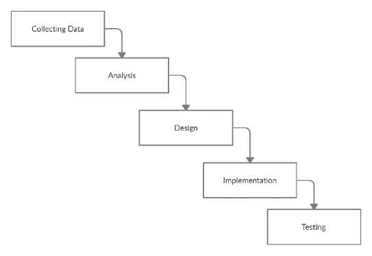
Figure 1. Waterfall Method
The data collection process in this research was obtained from direct observation of the school environment and interviews with school staff. The data collected is the SDN 3 Lukluk environment.
-
2.2. Analysis
The next step after collecting data is software analysis. The software analysis in this research is as follows:
-
a. Software requirements
Requirements for applications such as applications that can display building and room names from SDN 3 Lukluk environment. Another functional requirement is to be able to rotate, shrink, enlarge, and move the object displayed by the marker. Finally, the system can take pictures with the camera.
-
b. Software Input and Output
To be able to determine the software work system to be designed, it requires input and output of the software. The input required from this application is a marker, in this application the marker used is a QR code. This QR code is used to determine where the AR object will appear by scanning it through the camera. The output of this application is that when the camera scanning the marker has been successfully scanned, a 3D object of SDN 3 Lukluk will be displayed which provides information about the school environment.
-
c. Software Limitation
The limitation in this application is that the application only displays 3D Object of SDN 3 Lukluk environment. Another limitation of this application is the Android operating system which is at least version 4.4 and above.
Design is the stage where the developer starts designing the design of applications such as 3D objects, use case diagrams, and activity diagrams that will explain the overall software design [5]. At this stage, the application process flow is also used to explain the design of the software. The design of this application is as follows:
-
a. Application Process Flow
To describe the flow of the application process that will run, a flowchart is used to explain it. The flowchart of this application is as follow:
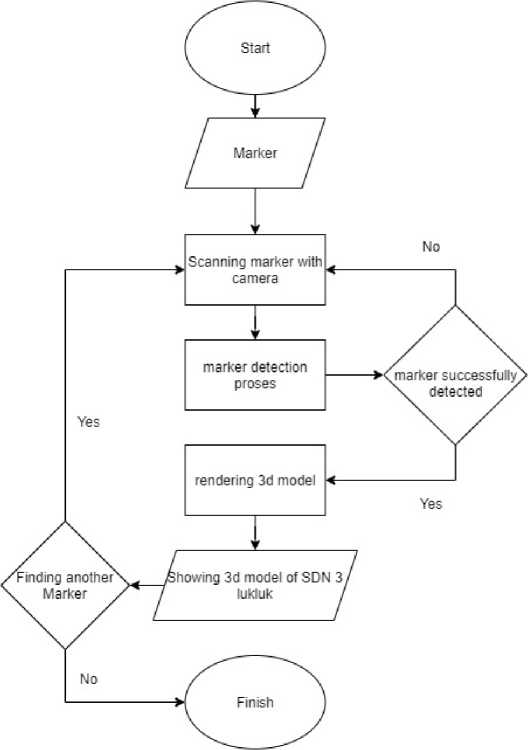
Figure 2. Application Process Flowchart
The initial step of the process begins with preparing a marker, then the marker is scanned using a camera, the marker detection process is carried out and if the marker is not detected successfully, the marker scanning process must be done again. If the marker is detected successfully, the application will render the object and display the SDN 3 Lukluk 3D object. The Process repeats again if the user decides to scan another marker.
-
b. Use Case Diagram
The use case diagram illustrates the process of anything that can be accessed by the user. In this application there is a process of starting the application, displaying the AR menu, displaying the help menu, displaying the developer menu, and the process of exiting the application. The use case diagram used in this application is as follow:
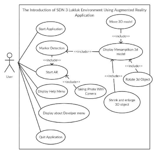
Figure 3. Use case diagram
-
c. Activity Diagram
Activity Diagram is a description of the flow of activities in this application [5]. some explanations of the Activity Diagram in this application are as follows:
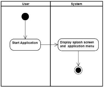
Figure 4. Activity diagram starting application
The activity diagram above describes the process when the user runs the application. The system will display the application splash screen and after a few seconds, the application will display the main menu.
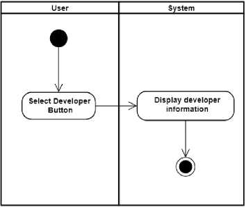
Figure 5. Activity Diagram Developer
The activity diagram above describes the process when the user presses the “Developer” button. The application will display the “Developer” menu which contains some information about the developer of the application.
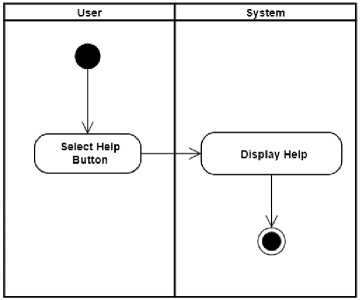
Figure 6. Activity Diagram Help
The activity diagram above describes the process when the user presses the “Help” button. The application will display the “Help” menu which contains information about how to use the application.
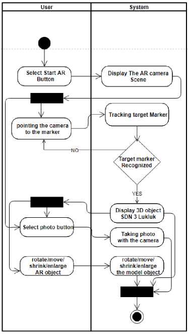
Figure 7. Activity Diagram Start AR
The activity diagram above describes the process when the user presses the “Start AR” button. The application will use the camera and a menu will appear on the screen. The menu has two-button, “photo” and “back” button. The “photo” button will take a photo with the camera and save it to the device and the “back” button will take the user to the main menu. If the user points the camera at the marker, the application will track the marker. The 3D object of SDN 3 Lukluk will be displayed if the marker is recognized and the user can move, rotate, shrink, and enlarge it. The user needs to point the marker again if the marker is not recognized.
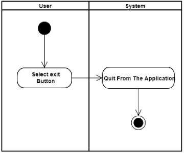
Figure 8. Activity Diagram Exit
The activity diagram above describes the process when the user presses the “Exit” button which will make the user exit the application.
d.
3D object Design
At this stage of designing a 3D object, an object will be designed in accordance with the data collected. 3d objects created with the Blender application. The 3D object that is created is as follows:
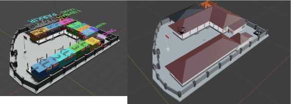
Figure 9. 3D object
This section discusses the implementation and testing of software that has been created. implementation and testing is as follows:
This section displays the results of the application implementation in the form of screenshots. The screenshots of the application are as follows:
a. Splash Screen

Figure 10. Splash Screen
-
b. Main Menu

Figure 11. Main Menu
c. Help Menu
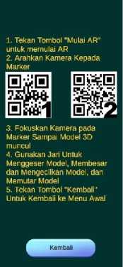
Figure 12. Help Menu
d. Developer Menu

Ida Bhujangga Bagus Dili Putra NIM. 1708561061
I Gede Arta Wibawa, S.T., M.Kom
NIP. 198310222008121001
Kembali
Figure 13. Developer Menu
-
e. AR object
-
• SDN 3 Lukluk
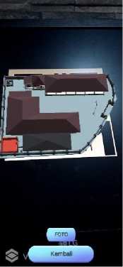
Figure 14. AR SDN 3 Lukluk
• SDN 3 Lukluk with information
f.
g.
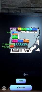
Figure 15. AR SDN 3 Lukluk with information
Move/Shrink/Enlarge/Rotate Object
Photo
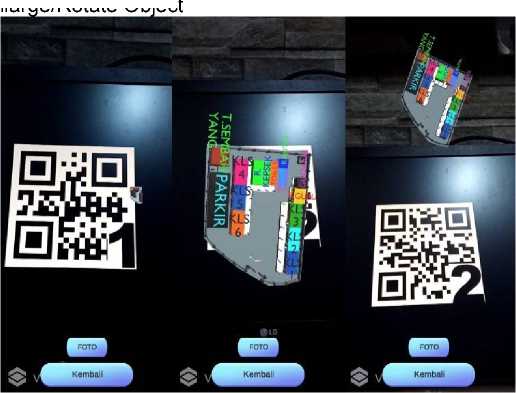
Figure 16. Move/Shrink/Enlarge/Rotate Object
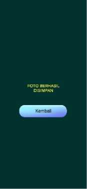
Figure 17. Photo
Testing on this application is carried out using Black-box testing. This Black-box testing aims to show the function of the software that has been made regarding how to operate. Black-box testing is carried out to check the functionality of whether the designed application is in accordance with the expected results or not [8]. This test is carried out by trying to run the application on several different devices, the devices used are Redmi 9 and Redmi 4X. From the testing process, the following results were obtained:
Table 1. Black-box Testing
|
No |
Functional |
Expected Result |
Testing result |
|
1 |
Starting the application |
Display the Splash screen and main menu |
Success |
|
2 |
Pressing the "Help" button |
Displays the help menu that shows how to use the application |
Success |
|
3 |
Pressing the “developer” button |
Display the developer menu which contains the developer information |
Success |
|
4 |
Pressing the "Start AR" button |
The application uses the camera and Display the AR camera menu |
Success |
|
5 |
Tracking the target marker with camera |
Display the AR 3D object of SDN 3 Lukluk on the marker |
Success |
|
6 |
Pressing the “Photo” Button |
The camera will take a photo and save it to the device |
Success |
|
7 |
Press and hold with one finger and move the finger after the AR 3D object is displayed |
The AR 3D object will move according to finger movements |
Success |
|
8 |
Pinch the screen after the AR 3d Object is displayed |
The AR 3D object will shrink |
Success |
|
9 |
Stretch the screen after the AR 3d Object is displayed |
The AR 3D object will enlarge |
Success |
|
10 |
Press and Hold with two fingers and rotate the finger |
The AR 3D object will Rotate |
Success |
|
11 |
Pressing the “Back” button |
The application will take back the user to the previous menu/main menu |
Success |
|
12 |
Pressing the “Exit” button |
The application will close |
Success |
The augmented reality application in this research was built to be able to provide information about the school environment of SDN 3 Lukluk. The SDLC (Software Development Life Cycle) method with the waterfall model is used in developing the application. Augmented reality in this application is marker-based which can receive input in the form of predetermined markers and the output of this application is in the form of Augmented Reality 3D Object from the SDN 3 Lukluk environment. This application is made with Unity-3D with an additional library, Vuforia for Augmented Reality development. The Application to create a model for this application is Blender. Based on the results of research using Black-box testing, it was found that the functional application had run well on different devices, all the feature successfully works, and the application able to display the Augmented Reality of SDN 3 school environment in 3D.
References
-
[1] E. Bobek and B. Tversky, “Creating visual explanations improves learning,” Cogn. Res.
Princ. Implic., vol. 1, no. 1, pp. 1–14, 2016, doi: 10.1186/s41235-016-0031-6.
-
[2] M. I. Maramis, A. S. Lumenta, B. A. Sugiarso, and J. T. Elektro-ft, “Augmented Reality
Pada Aplikasi Android Untuk Memperlihatkan Gedung Fatek,” J. Tek. Elektro dan Komput., vol. 5, no. 1, pp. 40–48, 2016, doi: 10.35793/jtek.5.1.2016.11542.
-
[3] A. Nugroho and B. A. Pramono, “Aplikasi Mobile Augmented Reality Berbasis Vuforia Dan
Unity Pada Pengenalan Objek 3d Dengan Studi Kasus Gedung M Universitas Semarang,” J. Transform., vol. 14, no. 2, pp. 86–91, 2017, [Online]. Available:
http://journals.usm.ac.id/index.php/transformatika/article/view/442/277.
-
[4] R. A. Setyawan and A. Dzikri, “Analisis Penggunaan Metode Marker Tracking Pada
Augmented Reality Alat Musik Tradisional Jawa Tengah,” Simetris J. Tek. Mesin, Elektro dan Ilmu Komput., vol. 7, no. 1, p. 295, 2016, doi: 10.24176/simet.v7i1.517.
-
[5] I. G. P. B. N. W. Prayoga, I. K. R. Arthana, and I. G. M. Darmawiguna, “Pengembangan
Aplikasi Augmented Reality Markerless Teknik Dasar Prenatal Yoga,” Prosiding Seminar Nasional Pendidikan Teknik Informatika (SENAPATI), 2017.
-
[6] N. L. M. D. A. Astita, A. F. Rochim, and K. T. Martono, “Aplikasi Augmented Reality Denah
SMP Negeri 36 Purworejo Menggunakan Mobile Android,” J. Teknol. dan Sist. Komput., vol. 3, no. 4, p. 456, 2015, doi: 10.14710/jtsiskom.3.4.2015.456-460.
-
[7] B. D. Atmojo, “Making of Helicopter Models With Polygonal Modeling Techniques in Mabur
Motor Game With 3D Blender,” Compiler, vol. 7, no. 2, p. 99, 2018, doi:
10.28989/compiler.v7i2.271.
-
[8] M. Adiwijaya, K. I. S, and Y. Christyono, “Perancangan Game Edukasi Platform Belajar
Matematika Berbasis Android Menggunakan Construct 2,” Transient, vol. 4, no. 1, pp. 128–133, 2015.
-
[9] I. B. M. Mahendra, “Implementasi Augmented Reality (Ar) Menggunakan Unity 3D Dan
Vuporia Sdk,” J. Ilmu Komput., vol. 9, no. 1, pp. 1–5, 2016.
-
[10] C. Tristianto, "Penggunaan Metode Waterfall Untuk Pengembangan Sistem Monitoring dan Evaluasi Pembangunan Pedesaan," J. Teknologi Informasi ESIT., Vol 8, no. 1, pp. 822, 2018.
202
Discussion and feedback