Designing Computer Network Subnetting with School Objects Using Cisco Packet Tracer 6.1
on
Jurnal Elektronik Ilmu Komputer Udayana
Volume 8, No 4. May 2020
p-ISSN: 2301-5373
e-ISSN: 2654-5101
Designing Computer Networks Subnetting With School Objects Using Cisco Packet Tracer 6.1
Desak Putu Sekar Merta Putria1, I Komang Ari Mogia2
aInformatics Engineering, Faculty of Mathematics and Natural Sciences, Udayana University Jalan Raya Kampus UNUD Bukit Jimbaran, Badung, Bali. Postal Code: 80364. Indonesia 1sekarmertaputri21@gmail.com
Abstract
The internet is one part that cannot be released in human life today. This increase in internet users causes the availability of ip to decrease. That is because users who will use the internet must have an IP. The availability of IPv4 is currently decreasing. To overcome these problems, IPv6 was made which was announced to replace the existence of IPv4. But another solution that can be taken is using subnetting. With subnetting, IP can be used optimally according to the needs of the host or can make efficient use of IP. And subnetting also functions to avoid congestion resulting from too many hosts on the physical network. And to connect between subnets, routing will be done. The design of computer network subnetting is expected to make efficient use of IP.
Keywords: subnetting, IP, Internet, Network, Routing
Internet (interconnection-networking) is all communication networks that use electronic intermediaries that can be connected to one another using Transmission Control Protocol / Internet Protocol (TCP / IP). Based on sources from the website of the Ministry of Communication and Information that internet users in the world in 2014 reached 2,892.7 million people, and it is projected that internet users in the world in 2018 will reach 3,600.2 million people. In Indonesia internet users in 2014 reached 83.7 million people and it is projected that in 2018 internet users in Indonesia will reach 123 million people. Based on these data it can be concluded that the more time passes, internet users both in Indonesia and in the world will experience an increase. An increase in internet users will correlate to the increasing number of IPs that must be provided. That is because to be able to connect to the internet the user must get an IP address that will be the identity of that user to be able to use the internet. However, with the IP currently available, it will cause the availability of IP now to be reduced. IP that is still used today is IPv4, so the availability of IPv4 has also been reduced. To anticipate these problems, IPv6 also appeared. IPv6 is declared to replace IPv4. However, other ways that can be used to anticipate these problems can also be done by doing subnetting. Subnetting itself is a division of the network so that IP can be used according to the needs needed. Subnetting can use the IP address as needed so that it can streamline the IP address. Subnetting is done by dividing the IP as needed and routing will be done which functions so that each subnet can communicate with each other.
There are several studies that discuss subnetting, namely research conducted by Lilik Eko Nuryanto with the title Concept of IP Address Subnetting for Internet Efficiency. This study discusses the subnetting conducted at a company that has 4 departments. The concept of subnetting is done to anticipate the occurrence of congestion caused by there are many hosts on a physical network. And there are also other studies written by Mochamad Husni with the title Design of Computer Network Routing Implementation Using Cisco. This research discusses
the making of a design to implement network routing using cisco. Subnetting design is made in a company by using IP class c. The design of this design is intended to streamline the use of IP.
IP (Internet Protocol) is a series of binary lifts consisting of 32 bits to 128 bits that function as addresses of users on computers in a computer network. A 32-bit IP is IPv4 and a 128-bit IP is IPv6. IPv4 has 5 classes, namely:
Table 1. Class on IP
|
Class |
First Octet (Decimal) |
First Octet (Binary) |
|
A |
1 – 127 |
0xxx xxxx |
|
B |
128 – 191 |
10xx xxxx |
|
C |
192 – 223 |
110x xxxx |
|
D |
224 – 239 |
1110 xxxx |
|
E |
240 - 255 |
1111 xxxx |
Source: https://informatikalogi.com/cara-menghitung-subnetting-ipv4/
Subnetting is the division of networks into two or more according to needs. Subnetting has a function to make efficient use and to avoid congestion caused by too many hosts on a physical network. To do subnetting that must be considered is the number of hosts available on IP and the desired host division. To classify IP addresses can be seen in the CIDR (Classless Inter-Domain Routing) table.
Table 2. CIDR Table
|
No |
Host to 2^n |
Number of Host |
Subnet Mask |
Pre Mask /32-n |
|
1 |
2^0 |
1 |
255.255.255.255 |
/32 |
|
2 |
2^1 |
2 |
255.255.255.254 |
/31 |
|
3 |
2^2 |
4 |
255.255.255.252 |
/30 |
|
4 |
2^3 |
8 |
255.255.255.248 |
/29 |
|
5 |
2^4 |
16 |
255.255.255.240 |
/28 |
|
6 |
2^5 |
32 |
255.255.255.224 |
/27 |
|
7 |
2^6 |
64 |
255.255.255.192 |
/26 |
|
8 |
2^7 |
128 |
255.255.255.128 |
/25 |
|
9 |
2^8 |
256 |
255.255.255.0 |
/24 |
|
10 |
2^9 |
512 |
255.255.254.0 |
/23 |
|
11 |
2^10 |
1024 |
255.255.252.0 |
/22 |
|
12 |
2^11 |
2048 |
255.255.248.0 |
/21 |
|
13 |
2^12 |
4096 |
255.255.240.0 |
/20 |
|
14 |
2^13 |
8192 |
255.255.224.0 |
/19 |
|
15 |
2^14 |
16386 |
255.255.192.0 |
/18 |
|
16 |
2^15 |
32768 |
255.255.128.0 |
/17 |
|
17 |
2^16 |
65536 |
255.255.0.0 |
/16 |
|
18 |
2^17 |
131072 |
255.254.0.0 |
/15 |
|
19 |
2^18 |
262144 |
255.252.0.0 |
/14 |
|
20 |
2^19 |
524288 |
255.248.0.0 |
/13 |
|
21 |
2^20 |
1048576 |
255.240.0.0 |
/12 |
|
22 |
2^21 |
2097152 |
255.224.0.0 |
/11 |
|
23 |
2^22 |
4194304 |
255.192.0.0 |
/10 |
|
24 |
2^23 |
8388608 |
255.128.0.0 |
/9 |
|
25 |
2^24 |
16777216 |
255.0.0.0 |
/8 |
Source: https://informatikalogi.com/cara-menghitung-subnetting-ipv4/
-
2.3. Routing
Routing is a process for directing different networks. Routing can connect between different networks so that different networks can communicate. When viewed from the packet delivery, routing can be divided into 2 namely:
-
• Direct Routing
Direct routing is addressing the host directly to the destination host without going through another host.
-
• Indirect Routing
Indirect routing is addressing a host that must go to another host first before being able to go to the destination host.
Routing has 3 types of configurations, namely:
-
• Minimal Routing
Minimal routing is a simple routing process on the local network.
-
• Static Routing
Static routing is routing on a network that has many gateways.
-
• Dynamic Routing
Dynamic routing is routing on networks that have more than one route.
Packet Tracer is a Cisco output application that functions for learning media in the field of networking as well as training and simulation research in the field of networking. The Cisco system was founded by Leonard Bosack and Sandy K. Lerner, they are former staff from Stanford University. The Cisco system was established in 1984. Until now, Cisco Packet Tracer has released the latest version, version 6.2, which can simulate application layer protocols, basic RIP routing, OSPF, and EIGRP.
In this subnetting, the IP used is 172.16.160.0 with subnetting distribution based on the needs of the school to be addressed. In this design a simulation will be made for subnetting purposes on:
-
a. Computer Lab
On the subnet for the computer lab will use IP 172.16.160.0 with netmask used ie / 26 which will provide the number of hosts 62. This netmask is used in order to meet the number of hosts in the computer lab that is 50 hosts. The network used is wired network. The subneting results obtained are:
Address : 10101100.00010000.10100000.00000000
(172.16.160.0)
(255.255.255.192)
(172.16.160.0) AND
(0.0.0.63)
(172.16.160.63) OR
Netmask : 11111111.11111111.11111111.11000000
IP Network : 10101100.00010000.10100000.00000000
Wildcard : 00000000.00000000.00000000.00111111
IP Broadcast : 10101100.00010000.10100000.00111111
IP that can be used : 172.16.160.1 until 172.16.160.62
-
b. Physics Lab
In the subnet for the physics lab will use IP 172.16.160.64 with netmask used ie / 26 which will provide the number of hosts 62. This netmask is used because in order to meet the number of hosts in the physics lab that is 50 hosts. The network used is wired network. The subneting results obtained are:
Address : 10101100.00010000.10100000.01000000
(172.16.160.64)
(255.255.255.192)
(172.16.160.64) AND
(0.0.0.63)
(172.16.160.127) OR
Netmask : 11111111.11111111.11111111.11000000
IP Network : 10101100.00010000.10100000.01000000
Wildcard : 00000000.00000000.00000000.00111111
IP Broadcast : 10101100.00010000.10100000.01111111
IP that can be used : 172.16.160.65 until 172.16.160.126
-
c. Chemistry Lab
In the subnet for the chemistry lab will use IP 172.16.160.128 with the netmask used is / 26 which will provide the number of hosts 62. This netmask is used because in order to meet the number of hosts in the chemical lab that is 50 hosts. The network used is a wired network. The subneting results obtained are:
Address : 10101100.00010000.10100000.10000000
(172.16.160.128)
(255.255.255.192)
(172.16.160.128) AND
(0.0.0.63)
(172.16.160.191) OR
Netmask : 11111111.11111111.11111111.11000000
IP Network : 10101100.00010000.10100000.10000000
Wildcard : 00000000.00000000.00000000.00111111
IP Broadcast : 10101100.00010000.10100000.10111111
IP that can be used : 172.16.160.129 until 172.16.160.190
-
d. Biology Lab
In the subnet for the biology lab will use IP 172.16.160.192 with netmask used ie / 26 which will provide the number of hosts 62. This netmask is used because it is to meet the number of hosts in the biology lab that is 50 hosts. The network used is wired network. The subneting results obtained are:
Address : 10101100.00010000.10100000.11000000
(172.16.160.192)
(255.255.255.192)
(172.16.160.192) AND
(0.0.0.63)
(172.16.160.255) OR
Netmask : 11111111.11111111.11111111.11000000
IP Network : 10101100.00010000.10100000.11000000
Wildcard : 00000000.00000000.00000000.00111111
IP Broadcast : 10101100.00010000.10100000.11111111
IP that can be used : 172.16.160.193 until 172.16.160.254
-
e. Language Lab
On the subnet for the language lab will use IP 172.16.161.128 with netmask used / 26 which will provide the number of hosts 62. This netmask is used because it is to meet the number of hosts in the language lab that is 50 hosts. The network used is a wired network. The subneting results obtained are:
Address : 10101100.00010000.10100001.10000000
(172.16.161.128)
(255.255.255.192)
(172.16.161.128) AND
(0.0.0.63)
(172.16.161.191) OR
Netmask : 11111111.11111111.11111111.11000000
IP Network : 10101100.00010000.10100001.10000000
Wildcard : 00000000.00000000.00000000.00111111
IP Broadcast : 10101100.00010000.10100001.10111111
IP that can be used : 172.16.161.129 until 172.16.161.190
-
f. Library
On the subnet for the library will use IP 172.16.161.0 with netmask used ie / 25 which will provide the number of hosts 126. This netmask is used in order to meet the number of hosts in the library that is 100 hosts. The network used is wireless network. The subneting results obtained are:
Address : 10101100.00010000.10100001.00000000
(172.16.161.0)
(255.255.255.128)
(172.16.161.0) AND
(0.0.0.127)
(172.16.161.127) OR
Netmask : 11111111.11111111.11111111.10000000
IP Network : 10101100.00010000.10100001.00000000
Wildcard : 00000000.00000000.00000000.01111111
IP Broadcast : 10101100.00010000.10100001.01111111
IP that can be used : 172.16.161.1 until 172.16.161.126
-
g. Administration, Principal's Room, Vice Principal's Room, Teacher's Room
In the subnet for Administration, Principals Room, Wakpeksek Room, Teacher Room will use IP 172.16.162.0 with netmask used ie / 25 which will provide the number of hosts 126. This netmask is used because it is to meet the number of hosts in TU, Principal Room , Wakpeksek Room, Teacher Room that is 100 hosts. The network used is wireless network. The subneting results obtained are:
Address : 10101100.00010000.10100010.00000000 (172.16.162.0)
Netmask : 11111111.11111111.11111111.10000000
(255.255.255.128)
(172.16.162.0) AND
(0.0.0.127)
(172.16.162.127) OR
IP Network : 10101100.00010000.10100010.00000000
Wildcard : 00000000.00000000.00000000.01111111
IP Broadcast : 10101100.00010000.10100010.01111111
IP that can be used : 172.16.162.1 until 172.16.162.126
-
h. Internet Park
On the subnet for the internet park will use IP 172.16.162.128 with netmask used ie / 25 which will provide the number of hosts 126. This netmask is used because in order to meet the number of hosts in the internet park that is 100 hosts. The network used is wireless network. The subneting results obtained are:
Address : 10101100.00010000.10100010.10000000
(172.16.162.128)
(255.255.255.128)
(172.16.162.128) AND
(0.0.0.127)
(172.16.162.255) OR
Netmask : 11111111.11111111.11111111.10000000
IP Network : 10101100.00010000.10100010.10000000
Wildcard : 00000000.00000000.00000000.01111111
IP Broadcast : 10101100.00010000.10100010.11111111
IP that can be used : 172.16.162.129 until 172.16.162.254
-
i. Server
On the server IP 10.10.10.0 will be used with netmask used ie / 30 which will provide host number 2.
-
j. IP Between Router
Untuk menghubungkan antara router dengan router maka digunakan IP mulai dari IP 172.16.163.0 dengan netmask yang digunakan yaitu /30 yang mana akan menyediakan jumlah host 2. Kemudian untuk menghubungkan antar router yang lainnya maka akan digunakan IP selanjutnya dengan netmask yang sama dan begitu pula selanjutnya.
To connect between routers and routers, IP is used starting from IP 172.16.163.0 with netmask used ie /30 which will provide the number of hosts 2. Then to connect between other routers the next IP will be used with the same netmask and so will the next .
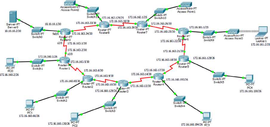
Figure 1. The subnetting design uses packet tracer
Figure 1 is the result of subnetting design that has been done, each subnet in the design has been able to communicate with each other. IP is loaded on the PC and router and for routing the router functions so that each network can communicate. Then also added a gateway for each pc or device that is there. Then routing is done for each router.
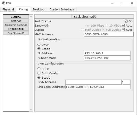
Figure 2. Charging IP on a PC or device
⅛P pco — □ ×
Physical Config Desktop Custom Interface
GLOBAL
Settings
Algorithm Settings
INTERFACE
FastEthernetO
__________________Global Settings
Display Name ∣PCQ
Gateway/DNS
O DHCP
(∙) Static
Gateway 1172.15.160.1
DNS Server ∣
Gateway/DNS Ipv6
O DHCP
O Auto Config
© Static
IPv6 Gateway ∣
IPv6 DNS Server I
Figure 3. Charging the gateway on a PC or device
Serial2∕0

FastEth ern et4∕0
FastEth ≡rn≡t5∕0
CZ Seria ∣6∕O
⅛P RouterO — □ X
Physical Config CLI
Static Routes
GLOBAL
Settings
Algorithm Settings
ROUTING Static _______RIP_______ INTERFACE __FastEth ern etO/O FastEth ernetl/O
Equivalent IOS Commands
Router>enable
Routertconfigure terminal
Ξnter configuration commands, one per line. Ξnd with CNTL∕Z. Router(config)#
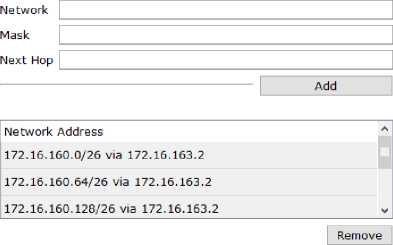
Figure 4. Routing on the router
After routing all routers, each subnet is connected and able to communicate. Testing of routing can be done by pinging IP from a PC or device on another subnet. Figures 2, 3, and 4 are the routing processes for each router that connects each subnet. Routing has been successful if it is in accordance with Figure 5.
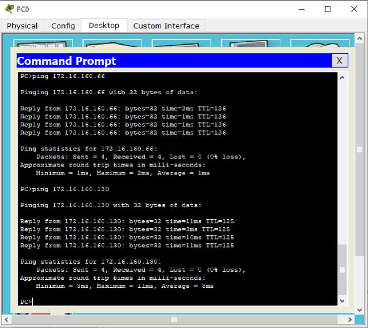
Figure 5. Testing for routing has been done
Based on the results of the design that has been made, subnetting can function to streamline the existing IP by dividing it into different networks by doing subnetting. In addition to streamlining IP, subnetting also functions to break down and make it possible to add or reduce the number of hosts that can connect to the network. In this design, a tool called packet tracer is used. The design that is made is still simple where the subnetting process is made manually and routing is done by static routing. Further development can be done by subnetting with different designs and applying the existing routing algorithm.
References
-
[1] Hendro. Hartono. “Penghitungan Subnetting Secara Otomatis”, ANGKASA, vol. 2, no. 1, 49 – 56, 2010.
-
[2] Mochamad. Husni, “Desain Implementasi Routing Jaringan Komputer dengan Menggunakan Cisco”, Jurnal Teknologi Informasi, vol. 3, no. 1, 43 – 50, 2012.
-
[3] Nuryanto. Eko, “Konsep Subnetting IP Address untuk Efisiensi Internet”, ORBITH, vol. 11, no. 1, 68 – 73, 2015.
-
[4] Fernadi. H S, Naemah. Mubarakah, ”Perancangan Virtual Local Area Network (VLAN) dengan Dynamic Routing Menggunakan Cisco Packet Tracer”, SINGUDA ENSIKOM, vol. 10, no. 28, 110 – 114, 2015.
452
Discussion and feedback