Coral Rock Thickness Grounding System Switchyard Substation In Clay
on
Journal of Electrical, Electronics and Informatics, p-ISSN:2549-8304 e-ISSN:2622-0393
23
Coral Rock Thickness Grounding System Switchyard Substation in Clay
I Gusti Ngurah Janardana1, I Wayan Arta Wijaya2
-
1,2 Departement of Electrical Engineering, Faculty of Engineering Udayana University, Bukit Jimbaran
Bali, Indonesia
Abstract - The grounding of the equipment at the substation switchyard location is given a layer of coral about 10 cm above the ground surface to reduce the tension difference on the ground surface and increase the resistance of the human feet around it. The purpose of this study was to determine the thickness of the coral in the grounding system of switchyard equipment in clay. This research analysis method calculates the results of the coral thickness value to achieve the step voltage and touch voltage values according to the IEEE Std 80-2013 standard so that it can provide safety for the equipment and people around it. The results of this study are that the thickness of the coral 0.15 meters produces a touch voltage value = 150.3675 volts (dry conditions) and 148.63 volts (wet conditions) and the step voltage is the smallest and best with a value = 206.83 volts ( dry conditions) and 163.98 volts (wet conditions when compared to the thickness of the coral 0.08 meters to 0.14 meters, so it is concluded that the thickness of the coral is best to be installed at the substation on clay of 0.15 meters is good when the soil and coral are wet or dry, so that it has an impact on the function of the grounding system to function properly and safely for equipment and humans.
Index Terms — Coral, Earthing, Clay.
-
I. INTRODUCTION1
The thickness of the coral affects the allowable touch voltage and step voltage values. According to IEEE Std 802013, the thickness of the coral layer is between 0.08 and 0.15 meters with a disturbance time of 1 second depending on the type/soil texture where the equipment is located [1]. The results of the research on installing coral stone on limestone soil dry conditions with a coral thickness of 0.15 m obtained a touch voltage value of 163.4038 volts and 157.7230 volts for wet soil conditions, while the step voltage is 227.0790 volts for dry soil conditions and 204, 0530 volts in wet ground conditions. Complementing research on the thickness of coral in the earthing of the entire existing soil texture. It should be noted that each type of soil texture has a different soil resistance value and causes a need for a different type of earthing and causes the step voltage and touch voltage to occur to be different, which in turn has an impact on the difference in the thickness of the coral needed at each location. each soil texture. The specific objective of this study was to find the thickness of the coral from the grounding system of the substation switchyard equipment on the texture of clay so that the step voltage and touch voltage are safe according to standards. The results of this study are expected to be used
as a reference for installing coral in the substation area.
Some references that support this research are:
-
1. Research on step voltage and touch voltage on hard clay soil results in a touch voltage in a dry state of 153.5615 volts and in a wet state of 152.0702 volts, the results of a step voltage in a dry state of 188.5057 volts and in a wet state of 182.8265 vol[2].
-
2. Research on grounding in sandy soil obtained results, the touch voltage value was 223.51 Volts, the step voltage value was 1188.69 Volts [3].
-
2.2 Current Through the Human Body
If the current that passes through the human body is greater than the current that affects the muscles, it will cause people to faint or even die, this is because the electric current affects the heart so that the heart stops working and blood circulation does not work [4].
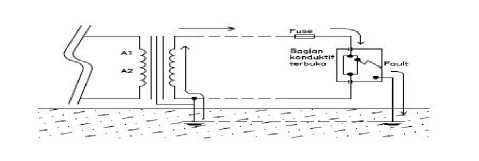
Figure 1. Path for Fault Current[4].
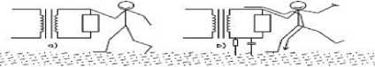
Figure 2. Hazards in systems without grounding [4].
(a) Apparent safety: no clear path for shock current
(b) Actual hazard: shock current due to ground resistance and capacitance.
-
2.3 Permitted Touch Voltage
The size of the touch voltage criteria and the permissible disturbance duration are shown in Table 1 below.
TABLE 1
PERMITTED TOUCH VOLTAGE AND
INTERRUPTION DURATION[5].
|
No |
Interruption Time t (seconds) |
Touch Voltage (Volts) |
|
1 |
0,1 |
1980 |
|
2 |
0,2 |
1400 |
|
3 |
0,3 |
1140 |
|
4 |
0,4 |
990 |
|
5 |
0,5 |
890 |
|
6 |
1,0 |
626 |
|
7 |
2,0 |
443 |
|
8 |
3,0 |
362 |
-
2.3.1 Permissible Touch Voltage Calculation
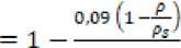
Before calculating the touch stress, it is necessary to find the reduction factor using the following equation:
C_(s 0.08)=1-(0.09 (1-p/p_s ))/(2h_s+0.09)
(1)
touch stress calculation using the following equation:
Ef70 = [1000+l⅛Cs]^
(2)
With description:
-
= permissible touch stress for a person weighing 70 kg (V)
-
= resistivity of coral (Ω-m)
-
= soil resistivity under the coral layer (Ω-m)
= reduction factor
-
= thickness of coral layer (m)
t = length of time of disturbance (s)
-
2.4 Permissible Step Voltage Criteria
The criteria for step voltage and permissible disturbance duration can be seen in table 2. The voltage that arises between the two feet of a human standing on the ground which is being flowed by ground fault current without
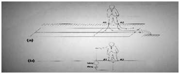
Figure 3 Step Voltage on Humans On Grounded Equipment With description:
= First human foot contact in the grounding area
= Second foot contact from human on ground area
= Equivalent voltage that arises in the human body
= Replacement resistance between A1,A2 and Ground Permissible step stress criteria can be calculated using equation [7]:
O,ll⅛
^i so = [lθθθ + 6 Es.p∩ Jts
(3)
Information:
= Allowable step voltage criterion (Volts)
= human body resistance ( ohm
= Reduction factor for the resistivity value of the soil surface = 0.6
-
= soil resistivity of the surface of the coral layer (ohmmeter)
-
= Long interruption (Seconds)
-
= The human body constant at a body weight of 50 kg
For a body weight of 70 kg is 0.157
-
6 = Series resistance of both legs.
-
TABLE 2
PERMITTED STEPS VOLTAGE AND INTERRUPTION
|
DURATION[5] | ||
|
No |
Interruption time t (second) |
Step Voltage (Volts) |
|
1 |
0,1 |
7000 |
|
2 |
0,2 |
4950 |
|
3 |
0,3 |
4040 |
|
4 |
0,4 |
3500 |
|
5 |
0,5 |
3140 |
|
6 |
1,0 |
2216 |
|
7 |
2,0 |
1560 |
|
8 |
3,0 |
1280 |
-
2.5 The Function of Using Coral at the Substation
Gravel laying in the switchyard area for [8] :
-
1. So that the fault current flows directly into the ground and not along the ground surface area when the ground fault current occurs.
-
2. When the transformer is disturbed (transformer oil leaks) puddles of transformer oil can be prevented, if the oil catches fire, the spread of fire can be avoided and does not disturb other equipment in the area.
-
3. As a medium that provides a layer of high resistance between the personnel who step on it and the ground under the gravel, because the gravel serves as an insulator.
-
4. Do not interfere with the movement of people and equipment mobility in the switch yard.
-
5. The step size of people walking in the area can be reduced,
-
6. Inhibiting the growth of bushes and grass in the substation switchyard area.
The research was conducted at several locations with clay texture in the Regencies/cities: Badung, Tabanan, Gianyar from December 2021 to January 2022 for wet soil and June to August 2022 for dry soil.
-
3.2 Research Implementation Design
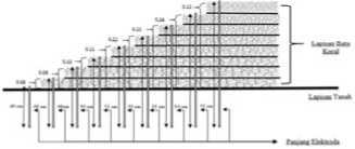
Figure 4. Coral thickness and electrode length
-
3.3 Research Flowchart
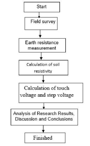
Figure 5. Research Flowchart
The following is an explanation in Figure 5:
Step 1. Get started
Preparation by preparing research materials.
Step 2. Field survey,
Determining the location of research looking for data on clay fields
Step 3. Measurement
Measure the resistance of the soil, and measure the resistance of the coral rock with each coral thickness of 0.08 m - 0.15 m during the rainy season and dry season.
Step 4. Calculation of soil resistivity
Calculating the soil Rho (soil type resistance) of field clay and the addition of coral with variations in each coral thickness of 0.08 m – 0.15 m based on measurement data to be able to calculate the allowable step stress and touch stress.
Step 5. Calculation of step voltage and touch voltage Calculating the permissible touch stress and step stress based on the thickness of the coral so that the thickness of the coral that is best installed for earthing the substation on clay will be obtained.
Step 6. Analysis of the calculation results, discussion of the results and conclusions
The calculation of the allowable touch voltage is based on the thickness of the coral layer in the clay fields. Before calculating the touch stress, it is necessary to find the reduction factor based on the thickness of the coral from 0.08 meters to 0.15 meters using the following equation:
C_(s 0,08)=1-(0,09 (1-ρ/ρ_s ))/(2h_s+0,09)
So that with a thickness of 0.08 meters of coral,
C_(s 0,08)=1-(0,09(1-33,91/11,30))/(2x0.08+0,09)
C_(s 0,08)=1,72
By using the same formula, the value of the reduction factor for coral thickness is 0.08 meters to 0.15 meters. The soil type resistance in field clay in a dry state is 33.91 ohmmeters, while the soil resistivity value when given coral varies depending on the thickness of the coral. The results of the calculation of the touch voltage based on the thickness of the coral on the field clay in a dry state are as follows:
E_(t 70) =[1000+1,5ρ_s C_s ] 0,147/√t
E_(t 70) =[1000+1,5 x 11,30 x 1,72] 0,147/√1
E_(t 70)=151,2856 Volt
By using the same formula, the touch voltage value is obtained with a thickness of coral from 0.08 meters to 0.15 meters on field clay in a dry state as shown in the Table 3.
In the wet state and the resistivity of the coral is 10.67 ohm-m, the reduction factor is calculated as follows:
Et70 =[1OOO+1⅛CJ^
Et 70 = [IOOO + 1,5 x 10,67 x 3,82] ^-
Sf70 = 155,987Volt
The results of the calculation of the touch stress on wet soil and coral conditions obtained the Table 4.
TABLE 3
RESULT OF VOLTAGE CALCULATION TOUCH SOIL AND CORAL CONDITIONS DRY, CORAL THICKNESS 0.08 m-0.15 m
|
No |
ρ soil (Ohm-m) |
ρ coral (Ohm – m) |
Coral Thickness (m) |
Reduction Factor |
Touch Voltage (V) |
|
1 |
33,91 |
11,30 |
0,08 |
1,72 |
151,2856 |
|
2 |
33,91 |
11,05 |
0,09 |
1,69 |
151,1174 |
|
3 |
33,91 |
10,80 |
0,10 |
1,66 |
150,9531 |
|
4 |
33,91 |
10,42 |
0,11 |
1,65 |
150,7910 |
|
5 |
33,91 |
10,29 |
0,12 |
1,62 |
150,6756 |
|
6 |
33,91 |
10,17 |
0,13 |
1,59 |
150,5655 |
|
7 |
33,91 |
10,04 |
0,14 |
1,57 |
150,4756 |
|
8 |
33,91 |
9,79 |
0,15 |
1,56 |
150,3675 |
TABLE 5
CALCULATION RESULTS OF STEPS VOLTAGE CONDITIONS OF SOIL AND CORAL STONE DRY WITH VARIATION OF THICKNESS CORAL STONE 0.08m-0.15m
|
No |
ρ soil (Ohm – m) |
ρ Coral (Ohm – m) |
Coral Thickness (m) |
Reductio n Factor |
(Step Voltage(V ) |
|
1 |
33,91 |
11,30 |
0,08 |
1,72 |
211,94 |
|
2 |
33,91 |
11,05 |
0,09 |
1,69 |
210,98 |
|
3 |
33,91 |
10,80 |
0,1 |
1,66 |
210,02 |
|
4 |
33,91 |
10,42 |
0,11 |
1,65 |
209,70 |
|
5 |
33,91 |
10,29 |
0,12 |
1,62 |
208,74 |
|
6 |
33,91 |
10,17 |
0,13 |
1,59 |
207,79 |
|
7 |
33,91 |
10,04 |
0,14 |
1,57 |
207,15 |
|
8 |
33,91 |
9,79 |
0,15 |
1,56 |
206,83 |
TABLE 4
TOUCH VOLTAGE CALCULATION RESULTS WET SOIL AND CORAL STONE
WITH CORAL STONE THICKNESS 0.08 m-0.15 m
|
No |
ρ soil (Ohm – m) |
ρ Coral (Ohm – m) |
Coral Thickness (m) |
Reductio n Factor |
Touch Voltag e (V) |
|
1 |
17,58 |
10,67 |
0,08 |
1,23 |
149,89 |
|
2 |
17,58 |
10,17 |
0,09 |
1,24 |
149,78 |
|
3 |
17,58 |
8,91 |
0,10 |
1,30 |
149,55 |
|
4 |
17,58 |
7,91 |
0,11 |
1,35 |
149,35 |
|
5 |
17,58 |
6,90 |
0,12 |
1,42 |
149,16 |
|
6 |
17,58 |
5,77 |
0,13 |
1,53 |
148,94 |
|
7 |
17,58 |
5,02 |
0,14 |
1,61 |
148,78 |
|
8 |
17,58 |
4,39 |
0,15 |
1,69 |
148,63 |
Calculation of step voltage in wet soil and coral conditions calculated the reduction factor based on the thickness of the
coral from 0.08 meters to 0.15 meters using the following equation:
4.2 Results of Step Stress Analysis
Calculation of allowable step voltage based on the thickness of the coral layer in the clay fields. So that with a thickness of 0.08 meters of coral,
So for a thickness of 0.08 meters of coral, it is obtained, 0,09 (1~^)
f, __ 10 &7
s0 08 2x0.08+0,09
^s 0.08 = 1-23
The results of step voltage calculations based on a thickness of 0.08 meters of coral on field clay in a wet state are as follows:
s 0,08 - 1
2x0.08+0,09
Es 70 ¾70 ⅞70
= [1000 + 6ps Cj ⅛
= [1000 + 6 x 17,58 x 1,23] ^y-
= 177,37 Volt
Cf 0,08 - 1'^2
The results of step voltage calculations based on a thickness of 0.08 meters of coral on dry field clay are as follows:
^s 70
¾70
¾70
= [1000 + 6ps CJ ^⅛-
= [1000 + 6 X 33,91 x 1,72] ^y-
= 211,94 volt
-
4.3 Discussion
The calculation results show that as the thickness of the coral increases, the step voltage decreases and with the same thickness the step voltage in the dry state is greater than the step voltage in the wet state. Based on IEEE Std 80-2013 recommends a layer thickness of coral between 0.08 to 0.15 meters with a disturbance time of 1 second depending on the type/soil texture of the location of the equipment. safe (good) but the thickness of 0.15 meter
coral has the best value in wet and dry conditions on Clay Fields
TABLE 6
RESULT OF STEPS VOLTAGE CALCULATION WET SOIL AND CORAL STONE CONDITIONS WITH 0.08m-0.15m THICKNESS VARIATION WITH
VARIATION OF THICKNESS 0,08m-0,15m
|
N o |
ρ soil (Ohm – m) |
ρ Coral (Ohm – m) |
Coral Thick ness (m) |
Reductio n Factor |
(Step Voltage(V) |
|
1 |
17,58 |
10,67 |
0,08 |
1,23 |
169,36 |
|
2 |
17,58 |
10,17 |
0,09 |
1,24 |
168,88 |
|
3 |
17,58 |
8,91 |
0,10 |
1,30 |
167,91 |
|
4 |
17,58 |
7,91 |
0,11 |
1,35 |
167,06 |
|
5 |
17,58 |
6,90 |
0,12 |
1,42 |
166,23 |
|
6 |
17,58 |
5,77 |
0,13 |
1,53 |
165,31 |
|
7 |
17,58 |
5,02 |
0,14 |
1,61 |
164,61 |
|
8 |
17,58 |
4,39 |
0,15 |
1,69 |
163,98 |
Method. JETri, Volume 15 (2). Jakarta: Jurusan Teknik Elektro Fakultas Teknologi Industri Universitas Trisakti.
-
[8] Latif, A. 2016. Probabilitas Tegangan Sentuh dan Tegangan Langkah di Lokasi Rencana Gardu Induk 500 kV Antosari. Bali: Universitas Udayana.
Based on the results of the study it can be concluded that the thickness of the coral 0.15 meters produces a touch voltage value = 150.3675 volts (dry condition) and 148.63 volts (wet condition) and the smallest and best step voltage with a value = 206.83 volts (dry conditions) and 163.98 volts (wet conditions when compared to the thickness of the coral 0.08 meters to 0.14 meters, the thickness of the coral is best to be installed at the substation on clay fields of 0.15 meters both on when the soil and coral are wet or dry, so that the impact on the function of the grounding system functions properly and is safe for equipment and humans
References
-
[1] Agung, J. 2015. Perancangan Sistem Pengetanahan Peralatan di Gardu Induk PLTU IPP (Independent Power Producer) Kaltim 3. Malang : Universitas Brawijaya.
-
[2] Suciawan, IPN. Janardana, IGN, Wijaya, IWA. 2021. Pengaruh Ketebalan Batu Koral Pada Tanah Lempung Dan Tanah Berpasir Terhadap Tegangan Langkah Dan tegangan Sentuh. Jurnal SPEKTRUM; Volume 8 No. 1 Maret 2021.
-
[3] Mahadewi, KM., Janardana, IGN., Wijaya, IWA., 2019. Analisis Tegangan Langkah dan tegangan Sentuh Serta Perencanaan Sistem Pembumian Pada Pembangunan Substation VVIP. Di Bandara Internasional I Gusti Ngurah Rai Bali. Journal SPEKTRUM Volume
-
6, No. 1 Maret 2019. Jimbaran : Program Studi Teknik Elektro Universitas Udayana.
-
[4] Suartika M. 2017. Sistem Pembumian (Grounding) Dua Batang Sistem Pengaman Tenaga Listrik. Bali: Universitas Udayana Bali.
-
[5] ] IEEE Standard 80 - 2000. (2013). Guide For Safety In Ac Substation Grounding. New York
-
[6] Tanjung, A. 2015. Analisis Sistem Pentanahan Transformator Distribusi di Universitas Lancang Kuning Pekanbaru. ISSN: 16932390 Jurnal Sains, Teknologi dan Industri, Volume 12 (2). Pekanbaru: Jurusan Teknik Elektro Fakultas Teknik Universitas Lancang Kuning.
-
[7] Kamal, J, Abduh, S. 2018. Perancangan Sistem Pentanahan Gas Insulated Switchgear 150 kV Pulogadung dengan Finite Element
Discussion and feedback