PROPROTOTYPE DESIGN OF WATER LEVEL CONTROL SYSTEM BASED ON PID CONTROLLER IN PLTMH
on
Journal of Electrical, Electronics and Informatics, Vol. 4 No. 2, August 2020
53
Prototype Design of Water Level Control System Based on PID Controller in PLTMH
I Nyoman Budiastra1, A.A Maharta Pemayun2
-
1,2Department of Electrical Engineering Faculty of Engineering, Udayana University Badung - Bali, Indonesia
Abstract— One of the development of technological innovations in the field of control systems in all aspects of life is needed to maintain the stability of the work of a system, PID control to maintain the speed of water flow in the supply pipe in order to maintain the rotating speed of turbines Micro Hydro Power Plants (PLTMH) is very necessary because to maintain the generator rotational speed remains stable. To maintain the stability of the water flow, a sluice gate is needed to regulate the flow of water that comes out of the reservoir to the stockpile, the sluice is called a valve that can be controlled with a microcontroller that will open and close in accordance with the data value of the Water Flow Sensor attached to the pipe. Simulation of Water Flow Sensor with PID control is used to simulate the MHP system with PID control by comparing the output if the PID value is changed.
Index Terms — Microkontroler, PID, PLTMH , Valve, Waterflowsensor.
One of the development of technological innovation in the field of control systems in all aspects of life is needed to facilitate human work, for example in aspects of industrial life. An example of developing a control system is the control of the speed of water flow in a stockpile to maintain the rotating speed of a Micro Hydro Power Plant (PLTMH) turbine. The stability of PLTMH is very necessary because to keep the rotating speed of the turbine connected to the generator remains stable.
To maintain the stability of the flow of water needed a sluice to regulate the flow of water that comes out of the reservoir to the stockpile, the sluice is called a valve that can be controlled with a microcontroller by comparing the sensor data attached to the pipe.
Based on this background, the writer will design and make a simulation of the reservoir floodgate control system where there is an electric valve that will work to regulate the size of the reservoir water opening. This tool also utilizes Arduino Uno as a controller and water flow sensor is used to determine the flow of water. This tool can be used for practicum activities in the Control Systems Laboratory
State of the Art Review
According to [1] Sri Sukarni Katamwatiningsih (2014) in the research of Micro Power Plants (PLTMH) to
determine the height and flow of water in Ciater Subang, West Java. As for using the experimental method by operating a PLTMH tool with variations in changing the height and flow of water. From the experimental results, the greater the price of h and Q, the greater the P produced. So that from this experiment we can be implemented in PLTMH by knowing the height and maximum water discharge from water sources.
-
[2] Muhammad Ruswandi Djalal (2015) To support the optimal performance of micro hydro power plants (PLTMH), an appropriate control technology design is needed. Therefore in this research, a frequency control strategy based on Capasitive Energy Storage (CES) and PID will be discussed. CES is a device that can store energy quickly in the form of an electric field on a capacitor. To get optimal performance, the correct tuning for CES-PID parameters is needed. To get the optimal CES-PID parameters in this MHP, the Cuckoo Search Algorithm (CSA) artificial intelligence method is used. The simulation results show that the application of CSA to the tuning of CES-PID parameters on PLTMH, can speed up settling time response to frequency changes and also improve system frequency overshoot response.
-
[3] Handry Setya Utama (2018) In his research, a prototype of a micro-hydro generator (PLTMH) was designed which was integrated to the complementary load (pseudo) as a voltage stabilizer and manual ecuquency. By utilizing the LG direct drive frontloading washing machine as a generator (PLTMH). Then the output water pressure or
flow meter is displayed using Arduino. The micro-hydro prototype is capable of producing a maximum voltage of 90V, a frequency of 123 Hz and a generator speed of 308 RPM using a water discharge of 127 mL / sec.Figures
Micro hydro power plants
Micro Hydro Power Plant (PLTMH) is a small-scale power plant with an output below 100 KW that utilizes the potential flow of water that exists in rural areas as a source of power such as irrigation channels, rivers or natural waterfalls. PLTMH has a simple construction, easy to operate, easy to maintain and with affordable investment costs so it is suitable to be applied to illuminate rural areas that are not affordable by the PLN electricity.
Preparation phase
At the preparation stage that needs to be done are:
-
1. Making an overview of the tools applied, as in Fig.1, the block diagram of the PLTMH system prototype design concept is shown
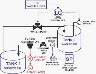
Fig. 1. Block Diagram
-
2. Look for references on the use of tools and materials used and how to work on them
-
3. Determine the time and place to work on tools and materials that have been prepared
Working Stage
-
1. Work on the power supply with a voltage source from PLN with a 220v AC voltage to a 24 Volt DC Voltage, which is coupled with a charger charger and batteries as a place to store DC electrical energy.
-
2. Working on water channel controller, this controller is based on arduino and water level sensor which is used as a measure of water level
-
3. The mechanical work of the water channel door, the mechanical assembly will be connected to the controller and calibrated with the water level sensor and the voltage source from the power supply.
-
4. Work on the module table by using angle iron.
-
5. The controller circuit is Arduino, water level sensor, supporting sensor and other components namely, resistor, capacitor, LED, transistor.
-
6. Connect the mechanical water channel door with the controller and power supply.
-
7. Making Water Wheel and Reservoir to collect water from the reservoir. And penstock waterways are connected using pipes from the reservoir to the Water Wheel. The pipe has been connected with a Water Flow sensor that is used to measure the speed of water discharge.
-
8. At this stage, tools that have been assembled, tested and analyzed for improvement and improvement of deficiencies so that the simulation tool for Water Flow Sensors with Arduino-based PID control can be operated optimally according to their functions and needs.
Completion and Finalization
At this stage, all problems and deficiencies are fixed, updated and innovated. After innovation and all deficiencies have been corrected, the Water Flow Sensor simulation tool with Arduino-based PID control is ready to be used as a teaching aid for the Electrical Engineering Control System lecture at Udayana University.
Tools
The work equipment used in the design, is divided into two parts, Equipment for manufacturing hardware and mechanics are:
-
1. Computers / laptops are used to design 3D reservoir plans and each component of the device with SketchUp software, Arduino controller programming using the Arduino IDE Software.
-
2. As well as other supporting equipment such as pliers, screwdrivers, saws, solder, ruler, cutter, voltmeter.
Workmanship stage
At the working stage begins by working on a series of each device, making a reservoir, making a circuit and position it together with a flow sensor.
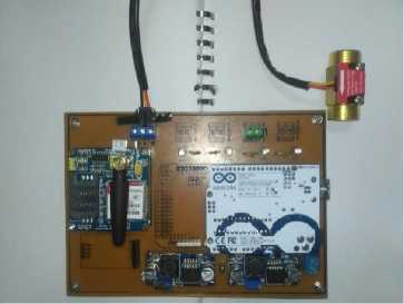
Fig. 2. Flow Control Circuit
After making the system to be tested, it will then create a simulation medium by installing several pipes and also a digital valve along with a water flow sensor. In Fig.2 hardware is shown which functions as a liquid or water flow control device. Furthermore, in Fig.3 and 4 the workmanship of the generator seat and the valve valve installation are shown.
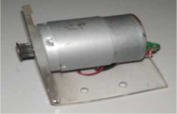
Fig. 3. Workmanship of The Generator Seat
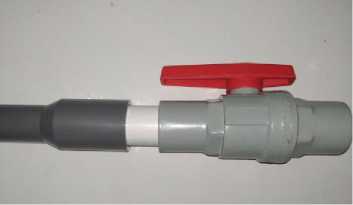
Fig. 4. The Valve Installation
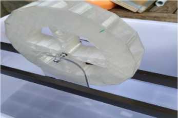
Fig. 5. Water Wheel Mounting Position
Power Supply
The power supply used by each device is 12 volts DC which is sourced from the step down which is installed in each device. For each device circuit will use a voltage source of 5 volts so a step down module is needed. Here two LM2596 modules are used, each to supply a microcontroller and a sensor. Tests conducted for power supply is to measure directly the output of the step down module used. Test images can be seen in Fig.6.
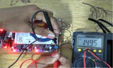
Fig. 6. Measurement of Input Voltage from Power Supply
Testing of Flow sensors and PID Systems
The system used in this tool is the PID, which serves to maintain the stability of the flow of water from the stocker connected to the reservoir. Large flowrate is needed so that the turbine rotation remains stable at 800Rpm which is 2 Liters / s. The following data comparison of water flow with and without PID:
TABLE I
Data Testing Without PID
|
Debit Air Terukur pada sensor |
Kondisi Valve Digital |
Over shoot |
|
2,8 L/s |
Terbuka 100% |
0.8 L/s |
|
2 L/s |
Terbuka 80% |
0 |
|
1,5 L/s |
Terbuka 45% |
0 |
In table 1 the test results are shown without using the PID control so that the water flow out is not constant or stable, the generator rotation becomes unstable.
Table 2 shows the test result data using a PID controller with a stable flow of water to 2 L / s. The complete test results are shown in table 4.2 below.
TABLE II
Data Testing With PID
|
Kp |
Ki |
Kd |
Over shoot |
Delay time (td) |
Rise time (tr) |
Peak Time (tp) |
Settling Time (ts) |
|
300 |
1 |
2 |
0.95 L/s |
6 s |
9s |
10s |
12s |
|
450 |
1 |
1.5 |
0.3 L/s |
4s |
6s |
7s |
10s |
|
500 |
1 |
1.5 |
0.85 L/s |
3s |
6s |
8s |
13s |
-
V. CONCLUSIONS AND RECOMMENDATIONS
Conclusions
Regulating the valve opening at 80% of the maximum opening can provide a flow rate of 2 L / s with little overshoot or no overshoot.
The reinforcement constant values P = 450, I = 1 and P = 1.5 produce the smallest settling time.
Use either SI (MKS) or CGS as primary units. (SI units are strongly encouraged.) English units may be used as secondary units (in parentheses). This applies to papers in data storage. For example, write “15 Gb/cm2 (100
Gb/in2).” An exception is when English units are used as identifiers in trade, such as “3½-in disk drive.” Avoid combining SI and CGS units, such as current in amperes and magnetic field in oersteds. This often leads to confusion because equations do not balance dimensionally. If you must use mixed units, clearly state the units for each quantity in an equation.
The SI unit for magnetic field strength H is A/m. However, if you wish to use units of T, either refer to magnetic flux density B or magnetic field strength symbolized as µ0H. Use the center dot to separate compound units, e.g., “A·m2.”
References
-
[1] Rr Sri Sukarni Katamwatiningsih, Pengaruh Ketinggian Dan Debit Air Terhadap Energi Listrik Yang Dihasilkan Pada Pembangkit Listrik Tenaga Mikro Hidro (PLTMH), artikel, 2014.
-
[2] Muhammad Ruswandi Djalal, Dwi Ajiatmo, Imam Robandi, frequency Control PLTMH dengan capasitive Energy Storage menggunakan Cucko Search Algorithm, Research Gate 2015.
-
[3] Handry Setya Utama, Medila Kusriyanto Prototype Pembangkit Mikrohidro terintegrasi beban komplemen, jurnal Teknoin Vol. 24 1 maret 2018.
-
[4] Barnawi M, M.O. Tjia. 1985. Rangkaian Dan Sistem Analog Digital.Jakarta: Erlangga.
-
[5] Abdur Rohman1, M. Agung Prawira Negara2, Bambang Supeno, Sistem Pengaturan Laju Aliran Air pada Plant Water Treatment Skala Rumah Tangga dengan Kontrol Fuzzy-Pid, Saintek 2017, V (1): 29-34
-
[6] Eltech. LCD (Liquid crystal display [Online]. Available: www.deltaelektronik.com
Discussion and feedback