Improving Performance Stability of Power System Java-Bali Interconnection with PIDPSS3B and PIDSVC Controllers
on
Journal of Electrical, Electronics and Informatics, Vol. 1 No.1, February 2017
Improving Performance Stability of Power System Java-Bali Interconnection with PIDPSS3B and PIDSVC Controllers
IBG Manuaba1, PA Mertasana2, M Mataram3, and CGI Partha3
Department of Electrical Engineering
Universitas Udayana
Kampus Bukit Jimbaran ibgmanuaba@unud.ac.id
Abstract - Modern electric power system that many its dynamic equipment continuously vulnerable to internal and external disturbances. On the condition of the disorder, it often happen oscillation in each part or between parts of the electrical system is interconnected. These oscillations become a major problem for the stability of the power system. Modern electrical control systems require a sustainable balance between power generation and demand varying loads. Power System Stabilizer and Static Var Compensator is a control device that is used to dampen low frequency oscillations and to provide additional feedback signal to stabilize the system. To increase the damping, system equipped with PSS generator that provides additional feedback to stabilize the signal in the excitation system. It is generally that the machine parameters changed by the load, so the dynamic behavior of the different machines at different operating conditions.
Design PIDPSS3B power system stabilizer and PIDSVC controller used aim to get performance and optimum damping. Design and optimization of the proposed has the ability to optimally dampen and suppress errors are minimal.
Index Terms— Power system stabilizer, static var compensator, PID,
-
I. INTRODUCTION3
Virtually every human activity today relate to electrical energy. The electricity production process is long and complex process to electrical energy can be used by users. Modern electrical system consists of a lot of equipment of different dynamic and a load to be continuously susceptible to the influence of internal and external interference. Under conditions of the influence of the disorder, it often happen oscillation in each section or cross section of the power system is interconnected.
An electromechanical oscillation in power systems is very challenging problem electrical engineers for many years. For this reason, the application controller that provides better damping for this oscillation is very important [10]. With
increasing distance transmission line charge, the implementation of power system stabilizer (PSS) may in some cases, do not provide enough damping to power swing in the area of inter-multimachine system. The stability of the power system is one of the most important aspects in the operation of the power system. This arises from the fact that the power system must maintain the level of frequency and voltage at the desired level, in any disturbance, such as a sudden increase in load, the loss of a generator or switch out of the transmission line during disturbances. [4]
The issue of the stability of the power system has become a very important issue to ensure a steady flow of electric power to customers. Models of electric power systems were very complicated to make are not easy to solve this problem. The problem will be compounded stability for large-scale electric power systems. Therefore, it is
important determining stabilization strategies that ensures stable system for the changes and ensure optimization of power system performance with the change.
-
II. METHOD
-
a. Power System Stabilizer (PSS)
The operational function of the PSS is to produce the proper torque on the rotor of the machine that are related such that the phase lag between the input exciter and electric engine torque compensated. The basic function of the PSS is to expand the limits of stability with modulation generator excitation to provide positive damping torque for power swing mode. PSS generate additional signals, which are added to control loop generating unit to produce positive damping. Additional stabilized signal is considered to be one of the speeds are comparable. The transfers function of i-th PSS given by [4]:
Gi =
κ jτ^ [(ι÷srli)(1+sτ3i)i
i ι+sτw L(1+sτ2i)(1+sT4i)J ιv j v 7
With Δωi is velocity deviation from synchronous speed. The output signal Ui to the regulator of the excitation system. Filter washout, is essentially a high pass filter, which is used to reset the steady state offset in the output of this PSS. Tw time constant value is usually not critical and can range from 0.5 to 20 s. PSS transfer function tuned to provide a phase-lead characteristics appropriate to compensate for the phase-lag between the reference input Δvs automatic voltage regulator and electrical torque
oscillation frequency range beyond Δ(O. Thus, the electric torque components in phase with the variation speed to improve damping. Block
diagram of the model PSS [8]:
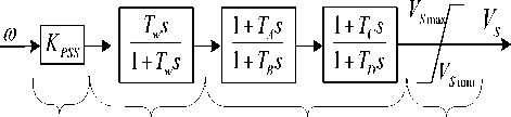
Gain Blok Washout Blok lead-lag Saturasi
Fig. 1. Block Diagram PSS
-
b. Proportional Integral Derivative (PID) Based Power System Stabilizer
PID controller algorithm is the most popular approach for industrial process control. Because the PID controller has a simple structure and durability in a wide range of operating conditions,
PID control scheme is widely used in most process control systems. The transfers function of the PID controller whose expression is [11] [12]:
Geds') = kpi+ ■ kdis
(2)
Where kp, ki, and kd respectively, the constant gain is proportional, integral and derivative. A block diagram of a PID-based power system stabilizer is shown in Figure 2 [3].
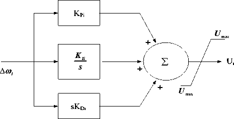
Fig. 2. PID-based power system stabilizer.
For PIDPSS block diagram is shown in Figure 3 as follows [1] [5]:
V
smax
Washout Circuit
Compensator
Filter
V .
smin
Limiter
kd4 Derivative
Fig. 3. Block Diagram PIDPSS
Additional excitation control, often referred to as PSS has become an important means to improve the low frequency oscillation damping. PSS PSS3B models have dual input consisting of electric power and frequency deviation angle rotor.
In particular, this model can be used to represent two different types of dual-input implementation stabilizer as described as follows: [6]
The stabilizer, the oscillation frequency range of the system, acting as a stabilizer electrical input power. It uses the speed or frequency of the input signal to generate mechanical power equivalent, to make the total signal is not sensitive to changes in engine power.
Stabilizer that uses a combination of speed (or frequency) and power. These systems typically use speed directly (i.e. without the phase-lead compensation) and adding a signal proportional to the electrical power to achieve the signal form desired stabilized.
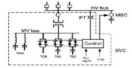
Fig. 5. System of SVC
Signals similar engine power is obtained using a signal. This signal is combined with electric power to generate electricity acceleration. Transducer time constant represented by the time constant T1 and T2. Washout time constant, rotor angular velocity, and engine power that comes each time constants represented by TW1 to TW3 [6]. Development is done with an embedded PID before a block diagram of a washout on the model of the power system. PIDPSS3B is the development of power system stabilizer PSS3B.
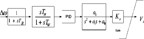
e. PID Static Var Compensator (PIDSVC)
Static Var Compensator (SVC) is connected to the generator exciter with Proportional-Integral-Derivative (PID). Based on the speed deviation ∆ω, PIDSVC regulate the flow generator so that the damping torque required can be channeled and damping out the oscillations.
+
Bref
VSVC
V
SI MAX min
VSVC
PID
sTw3 1+sTw3
1+A s+A s2
1+A s+A s2
1+A s+A s2
56
1+A s+A s2 78
PID
max
VSVC
Ks
Bmax
VSI1
1
1+sT
sT
K w1
s1 1+sT w1
+
VSI2
1 1+sT
sT
K w2
s21+sT
+2T"
Fig. 4. PSS type PSS3B with added PID
V
SI MIN
d.
SVC has a function to inject or absorb reactive power static control and that have a parallel connected output (output) is varied to maintain or control certain variables of the power system, especially bus voltage. SVC consists of TCR (Thyristor-Controlled Reactor), TCS (Thyristor Switched Capacitor) and filter. Filter function for handling high harmonics generated by TCR. SVC equipment is used to compensate for reactive power [2].
The working principle of SVC is by regulating the reactive power output of the SVC. Value system is an input voltage (input) for the controller, which then will adjust the firing angle thyristor. Thus SVC will provide reactive power compensation in accordance with the needs of the system.
Ks
1 + sTs
a0
s 2 + a 1 s
R ■ min
sTw
1 + sTw
1
1-T
Fig. 6. Block Diagram PIDSVC
fV. Model Multi Machine Overall
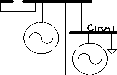
Generators connected in interconnection is assumed to consist of multiple machines (coupling) in each of the generating units which have the power and the machine generator unit do not affect each other machine in the unit of the power plant. The machines in the plant will react together simultaneously to overcome the impact of the swing of the other generating units. Linear system model based on multi-machine modeling Park assuming the resistors are ignored, the condition is considered balanced system, the core saturation generator ignored, and the load is considered as a static load. [7]
Δ U t-
KA
Δ U e

∆ U.
Δ ω
Governor
Ksg
1 + Ts sg
IΔ Yt
Δ sl
Sistem Eksitasi
~ Δ V1 “
1 + .Ta
VF
sKFi
■
K2,jj
1
1 + STR
sTW
1 + sTW
1
RG
- , Δ Pd
Δ T^
Turbine
1
1⅛
Δ E
K1,jj

1 κε + .Tε
K4,jj
δ δ A
K4
Teg bus
Fuzzy pre- compensated PID

s
K3
T„ + sK3 + 1
C
C 3, jj
f Δ E
K5
a0
S + a.+ali
qj
Fig. 7. Model Diagram linear multi machine
s
Figure 8 shows a flowchart for calculating the damping on PSS design based PID tuning starting power flow analysis, determination of the parameters of the system, electrical power system modeling and subsequent multi machine PSS tuning parameters and excitation system.
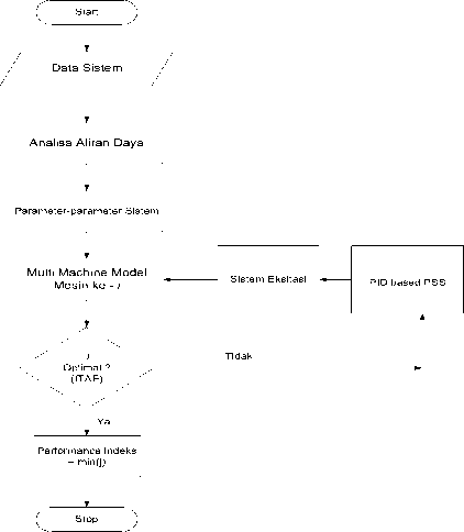
Fig. 8. A flow diagram for a multi machine
Based on the performance index J optimization
K6
δ Eq
K6
(minimization) problem can be expressed as:
Performance Index (PI) = min (J)
Subject to:
|
Kmin |
≤ |
Kp |
≤ |
Kmax |
|
K min |
≤ |
Ki |
≤ |
K max |
|
Km™1 |
≤ |
Kd |
≤ |
Kma |
|
K™™ |
≤ |
Ka |
≤ |
Kjnax |
III. RESULTS AND DISCUSSION
Electric power system data used includes two new plants with combined long complement the six plants are plants hydroelectric power plant Muara tawar and power plant Gas and steam Grati. The eighth generation is interconnected via a transmission line of 500 KV. Data of Java-Bali power system of 500 kV to be used is the data obtained from PT. PLN Transmission and Dividers Center Expenses (P3B) per consisting of 25 buses (with 1 piece of slack bus, bus generator 7 pieces and 17 pieces bus load), 30 lines, and 8 plants. In th is section, the simulation is done using
MATLAB. Modeling Java-Bali interconnection
used in this paper consists of a single synchronous generator with PSS3B and gain AVR. Single line diagram of the Java-Bali power system 500 kV is shown in Figure 9.
CILEGON 2
7
BEKASI
6
CAWANG

TANJUNG JATI

SURALAYA
1

NGIMBANG
T
CIBINON
5
10 CIRATA
MUARA
TAWAR 8
SAGULING
BANDUNG SELATAN
9 CIBATU

11
12
13
DURACAN
4
GANDUL
18 DEPOK
24
3
KEMBANGAN
17
GRESIK

16
AYA BARAT
23
14
19
TASIKMALAYA
25
BALARAJA
GRATI
UNGARAN
20
PEDAN

Fig. 9. Single line diagram Java-Bali interconnection system 500 KV
TABLE 1
Value Optimization for constants KP, KI, KD
|
PIDPSS3B |
G1 |
G2 |
G3 |
G4 |
|
Kp |
0.7512 |
0.7512 |
0.7512 |
0.7512 |
|
Ki |
0.1211 |
0.1211 |
0.1211 |
0.1211 |
|
Kd |
0.2508 |
0.2508 |
0.2508 |
0.2508 |
|
PIDPSS3B |
G5 |
G6 |
G7 |
G8 |
|
Kp |
0.7512 |
0.7512 |
0.7512 |
0.7512 |
|
Ki |
0.1211 |
0.1211 |
0.1211 |
0.1211 |
|
Kd |
0.2508 |
0.2508 |
0.2508 |
0.2508 |
In Table 1 show the PID PSS3B parameters that have been optimized.
Waktu (Detik)
Performansi Deviasi Sudut Rotor Generator 2 Muara Tawar
Performansi Deviasi Sudut Rotor Generator 7 Paiton
0.05
0.04
0.03
0.02
0.01
-0.01
50
100
-0.02 0
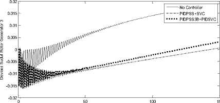
Performansi Deviasi Sudut Rotor Generator 3 Cirata
Waktu (Detik)
150
Waktu (Detik)
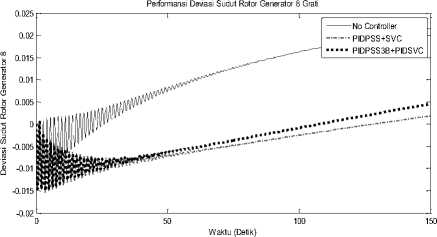
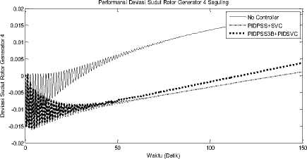
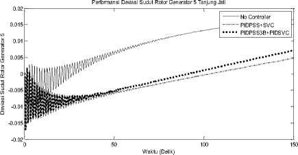
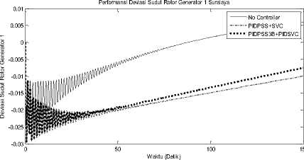
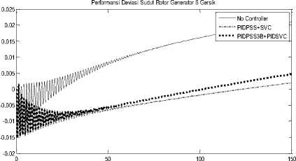
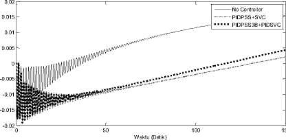
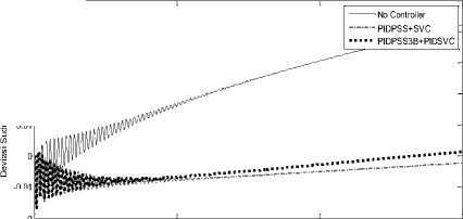
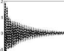
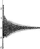
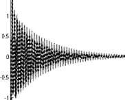
Fig. 10. Performance rotor angular deviation (pu) in the Java-Bali interconnection generator for each plant.
From Figure 10 showed that PIDPSS with PIDSVC reach steady state more rapidly than others. PIDPSS with PIDSVC showed better stability, which means that it has a better ability compared with other methods of damping.
x 10-4
Performansi Deviasi Frekuensi Generator 1 Suralaya
No Controller
PIDPSS+SVC
PIDPSS3B+PIDSVC
50 100 150
Performansi Deviasi Frekuensi Generator 6 Gersik
-4 x 10⁻⁴
05
-0.5
-1.5
50
100
Waktu (Detik)
-2 0
x 10-4
Waktu (Detik)
Performansi Deviasi Frekuensi Generator 2 Muara Tawar
3
No Controller
PIDPSS+SVC
PIDPSS3B+PIDSVC
150
Deviasi Frekuensi Generator 5 Deviasi Frekuensi Generator 4 Deviasi Frekuensi Generator 3
Waktu (Detik)
100
-2
0 50 100 150
Waktu (Detik)
Performansi Deviasi Frekuensi Generator 4 Saguling
-1.5
-2
0
50
100
1.5
-2
No Controller
PIDPSS+SVC
PIDPSS3B+PIDSVC
150
Waktu (Detik)
Performansi Deviasi Frekuensi Generator 5 Tanjung Jati
x 10-4
1
0.5
0
-0.5
-1
-1.5
50
100
15
Waktu (Detik)
0
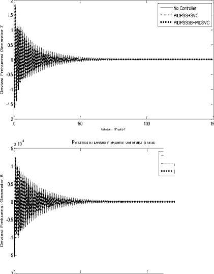
Performansi Deviasi Frekuensi Generator 7 Paiton
x 10-4 2
-2
1.5
15
05
-0.5
-1.5
Performansi Deviasi Frekuensi Generator 8 Grati
0.5
-0.5
-1.5
50
100
Waktu (Detik)
-2 0
No Controller PIDPSS+SVC PIDPSS3B+PIDSVC
Waktu (Detik)
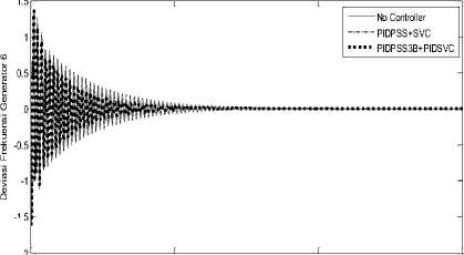
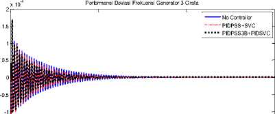
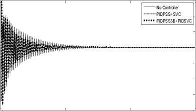
Fig. 11. Performance angular deviation in the frequency of generating the Java-Bali interconnection for each plant.
Comparison of the performance of the angular deviation frequency is shown in Figure 11. From the graph shows that performance by using PIDPSS3B with PIDSVC better than others.
TABLE 2
Performance Index
|
Performance Index | |
|
Method |
ITAE |
|
No Control |
460.9866 |
|
CPSS+SVC |
108.1126 |
|
PIDPSS+SVC |
93.8374 |
|
PIDPSS3B+PIDSVC |
66.5966 |
150
From Table 2 above, the results obtained indicate that the Java-Bali system multi machine 500 KV with PIDPSS3B and PIDSVC controller proposed has better ability than the other to minimize errors.
In this paper, optimization of power system stabilizer (PIDPSS3B) with PIDSVC proposed could improve the dynamic stability. With a performance index obtained at 66.5966. The proposed design has the capability to optimally dampen and suppress errors are minimal.
Acknowledgment
The author gratefully acknowledge the financial support for this study by the Directorate General of Higher Education (Directorate of Higher Education), University of Udayana with 2016 national competitive funding for fundamental research.
References
-
[1] A. Oonsivilai and B. Marungsri, “Stability Enhancement for Multi-machine Power System by Optimal PID Tuning of Power System Stabilizer Using Particle Swarm Optimization”, WSEAS Transactions on Power Systems, vol. 3, 2008, pp. 465-474.
-
[2] Abido, M.A., and Y.L. Abdel-Magid,"Coordinated design of a PSS and an SVC-based controller to enhance power system stability", Electrical Power and Energy Systems, pp. 695-704, 2003.
-
[3] D. Beta, D. Da, and T.K. Basu, “Design of P-I-D Power System Stabilizer for Multimachine System,” in Proc. 2004 IEEE India Annual Conf., pp. 446-450.
-
[4] H. Shayeghi, A. Safari, and H. A. Shayanfar, “Multimachine Power System Stabilizers Design Using PSO Algorithm”, International Journal Of Electrical Power and Energy Systems Engineering, 2008, pp. 226233.
-
[5] IBG Manuaba, M Abdillah, A. Soeprijanto, and Mauridhi Herry P., “Coordination of PID Based Power System Stabilizer and AVR Using Combination Bacterial Foraging Technique – Particle Swarm Optimization”, The 4th International Conference on Modeling, Simulation and Applied Optimization (ICMSAO), Kuala lumpur, Malaysia, April 2011, pp.508-514.
-
[6] IEEE Power Engineering Society, "IEEE Recommended Practice for Excitation System Models for Power System Stability Studies", IEEE std 421.5-2005, New York, USA, April, pp 23, 2006.
-
[7] Imam Robandi (2006), "Desain Sistem Tenaga Modern", Andi Offset, Yogyakarta, Indonesia.
-
[8] L.J.Cai, and I. Erlich (2003), "Simultaneous Coordinated Tuning of PSS and FACTS Controller for Damping Power System Oscillations in Multi-Machine Systems", IEEE Bologna Power Tech Conference, Bologng, Italy.
-
[9] N. Sinha, L. L. Lai, and V. G. Rao, “GA optimized PID controllers for automatic generation control of two area reheat thermal systems under deregulated environment”, Third International Conference on Electric Utility Deregulation and Restructuring and Power Technologies(DRPT), 2008, pp. 1186-1191.
-
[10] Ramos RA, Martins ACP, and Bretas NG, “An Improved methodology for the design of power system damping controllers”, IEEE Trans Power System, 2005, pp. 19381945.
-
[11] S. H. Hosseini, R. Rahnavard, and H. Kharrati, “Application of Genetic Algorithm to Design PID Controller for Power System Stabilization”, Available at: http://citeseerx.ist.psu.edu/. [Diakses 8 Februari 2009]
-
[12] W. M. Korani, H. T. Dorrah, and H. M. Emara, “Bacterial Foraging Oriented by Particle Swarm Optimization Strategy for PID Tuning”, IEEE International Symposium on Computation Intelligence in Robotic and Automation (CIRA), 2009, pp. 445-450.
23
Discussion and feedback