Design of Lighting Control with RTC Timer and SMS Using Microcontroller
on
Journal of Electrical, Electronics and Informatics, Vol. 1 No.1, February 2017
Design of Lighting Control with RTC Timer and SMS Using Microcontroller
I GAP. Raka Agung1, I GAK. Diafari Djuni H2
1Electrical Engineering Departement, Engeneering Faculty, Udayana University Bukit Jimbaran, Indonesia
E-mail: igapraka@yahoo.co.id
2Electrical Engineering Departement, Engeneering Faculty, Udayana University Bukit Jimbaran, Indonesia
Abstract - The purpose of this research is to make the switch to turn on and off lighting with time can be set based on certain conditions. Controller utilizes Arduino UNO microcontroller with input from DS1307 RTC IC, photodiode, IComSat V1.1 with the output of LCD display and lighting switch. In this study realized photodiode sensor to detect dark and light illumination, DS1307 RTC IC as a source of real-time equal to the time actually, IComSat v1.1 SIM900 GSM/GPRS Shield for Arduino to communicate with HP via SMS, switch circuit and drivers for turn on and off the load of lighting and Arduino UNO with programs that has been put into flash memory. Research results obtained are supporting components of the equipment control to turn on and off of lighting utilizing microcontroller can be realized and are functioning in accordance with the plan. Two lightings can already turn on and off based on the input time of the RTC (the default) and on off status can be checked by SMS. Both lightings can already be turn on and off by SMS messages sent from mobile HP and received by microconroller (IComSat) and feedback lighting conditions is already accepted by mobile HP corresponds to on and off lights condition.
Index Terms— microcontroller, SMS, lights, RTC, HP
-
I. Introduction4
The energy savings should continue to be done because the world energy reserves are depleting. One attempt to do is turn off the lights when not in use, and vice versa. With the advancement in the field of electronics timeliness to turn on and off lights can be done by using a timer. The use of such a light sensor photodiode to detect the dark and light also has some weakness. Weakness include optical surface sensors must be cleaned regularly so that light can still penetrate the surface. Required signal conditioning circuit so that the components that needed more. Weakness and failure timer and photodiode can be complemented by adding communication with SMS so that if there is a failure on a timer and photodiode sensor lighting can be controlled life and death wears the
mediation of SMS. Only if the photodiode sensor is not functioning status lights life and death can not be known through SMS. Research on the life and death time control lighting has been done. Similar observations have been made by Huda uses the microcontroller AT89S51 and SMS to control ON and OFF lighting [1]while Putra did the same thing but with microcontroller AT89S52[2]. Masinambow utilizing Arduino microcontroller and android phones to turn on and off electrical switches [3]. Fadhil utilizes ATmega16 microcontroller and DS1307 RTC timer to set aeroponic watering automatically [4]. Khan has been using DS1307 RTC to know in real time the level of generator fuel tank to detect fuel theft [5].
In this study used the three detector / equipment to detect so that the life and death of lighting can
be performed more reliably. By default lighting set life and death using DS1307 RTC timer [6]. To know whether the lights are already live or die wear sensor photodiode. Lighting can also turn on and off and conditions of life and death read wirelessly through SMS. Control of lighting wear life and death of SMS can be done whenever desired
-
II. method
Hardware block diagram of the equipment that will be realized can be seen in Fig. 1.
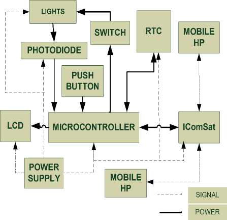
Fig. 1. Hardware block diagram of the equipment
This block diagram consists of block Arduino microcontroller[7], LCD [8], IComSat, lights and switches, photodiode, RTC, HP and the power supply. The center of the control system is located on a block of microcontroller Arduino that will control lighting through the switch block with status feedback signal derived from the photodiode. SMS communication with GSM network is done through IComSat[9]. RTC is a source of real time that will be setup so that the same as the actual time on earth (local time). LCD is used to display the test results so they can be seen by the operator or the researchers themselves for the completeness of the data to be analyzed.
To realize this equipment overall steps are as follows:
-
1. The design of the khardware
-
2. Assembling the hardware
-
3. The process of testing each circuit block and overall
-
4. Preparation and testing of the program in each block
-
5. The overall test is test program on the equipment that realized
Before testing the program on the hardware made in Proteus circuit simulation so that performance of the program can be seen on the circuit simulations and conducted repairs in order to get performance as planned.
Overall testing performed by combining all hardware and programs into a single entity, record the test results and perform analysis to obtain results in line with the design. If the results of the analysis to get things lacking in accordance with the result of design, improvements will be made to obtain the performance of the equipment in accordance with the design.
-
III. RESULTS AND DISCUSSION
Realization lighting controller utilizing the microcontroller equipped with RTC and SMS can be seen in Fig. 2 to 4.
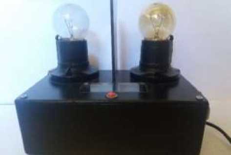
Fig. 2. Actual lighting controller utilizing a microcontroller
1
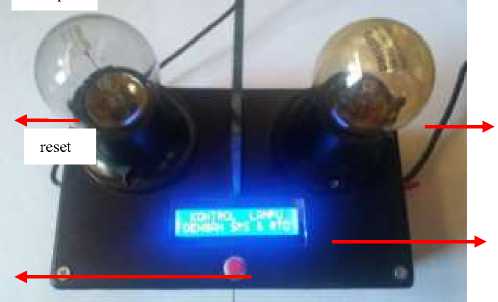
reset
Lamp 2
LCD
Fig. 3. Display appears on controlling lighting utilizing
microcontroller
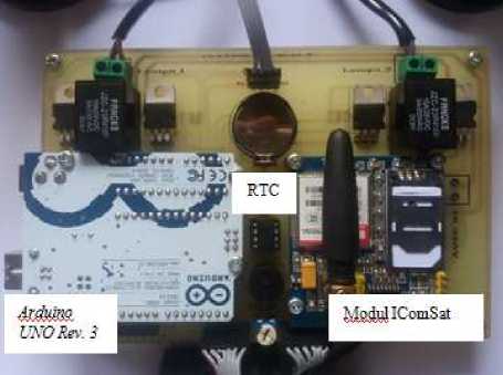
Fig. 4. Electronic devices lighting controller utilizing a microcontroller
"all lamp are ON”
" all lamp are OFF”
While some the conditions in Table I can be seen in Fig. 5 to Fig. 9.
1. Receive SMS: "SATU ON"
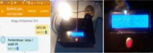
Fig. 5. Display condition at HP, lights and LCD when receive SMS "SATU ON"
Testing and Discussion Overall Equipment
A. Testing and Discussion Based Response IComSatV1.1-SIM900 Module Shield for Arduino
Testing sending SMS, SMS received on microcontroller display on the LCD, the command that is run on the lights and the reply SMS if the command was successfully implemented and if the command fails implemented can be seen in Table 1. This test is used to determine whether all parts of these controllers can functioning according to plan.
TABLE I
TESTING SENDING SMS, SMS RECEIVED ON HP STATIC DISPLAY ON THE LCD, THE COMMAND THAT IS RUN ON THE LIGHTS AND THE REPLY SMS IF THE COMMAND WAS SUCCESSFULLY IMPLEMENTED AND IF THE COMMAND FAILS
2. Receive SMS: "DUA ON"
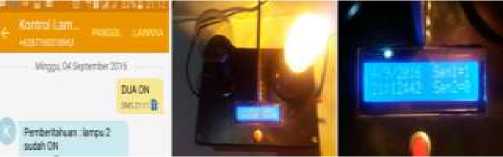
Fig. 6. Display condition at HP, lights and LCD when receive SMS "DUA ON"
3. Receive SMS: "ALL ON"
SMS Received
N SMS LCD Command (Based Sensor Readings)
o SEND DISPLAY be Run successful Fail
command command
Receive "SMS sign in
. SMS: to turn on the
“SATU ON” lamp1”
Turn on lamp1
" Notice: lamp1 " Notice: Error is ON " Condition "
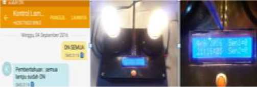
Fig. 7. Display conditions at HP, the lights and the LCD while receiving SMS "ALL ON"
2.
Receive
"SMS sign in
SMS: “DUA to turn on the
ON”
Receive
lamp2"
Turn on lamp2
" Notice: lamp 2 " Notice: Error
is ON
Condition "
""SMS sign in Turn on
3. SMS: “ALL to turn on all
ON”
Receive
lamp"
"SMS sign in
lamp1 and lamp2
" Notice: all lamp" Notice: Error
4. Receive SMS: "ALL OFF"
4. SMS: SATU to turn off the
OFF”
Receive
lamp1”
"SMS sign in
Turn off lamp1
5. SMS: “DUA to turn off the
OFF”
Receive
lamp 2" "SMS sign in
Turn off lamp2
6. SMS: “ALL to turn off all
OFF”
7. Receive SMS: “CEK”
lamp”
are ON"
Condition "
“Notice: lamp1 are OFF"
“Notice: lamp2 are OFF
Turn off lamp1 and lamp2
""SMS sign in Check
to check lamp lamp
status”
" Notice: Error Condition "
Notice: Error
Condition "
" Notice: all lamp" Notice: Error
are OFF"
Condition "
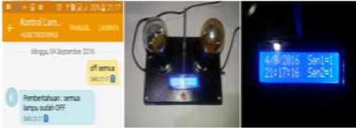
Fig. 8.Display condition at HP conditions, the lights and the LCD while receiving SMS "all off" "
Possibilities
notices:
status base
“lamp1 is ON”
on
on "lamp2 is OFF"
photodiode
"lamp1 is OFF” sensor
“lamp2 isi ON" condition
5. Receive SMS: "CHECK"
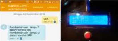
Fig. 9.Display condition at HP and the LCD while receiving SMS "check "
There are three other possibilities if microcontroller receive SMS "CEK" are lamp1 in OFF and lamp2 in ON or ON condition of the both lamps or OFF condition of the both lamps
The test results of Table I suggest that the lamp1 and lamp2 can already turn on and turn off of HP mobile corresponds to the SMS received by the microcontroller (IComSat). SMS feedback is sent to HP mobile is also already in the planning in accordance with ON and OFF conditions of the lights obtained from the condition into two photodiode.
-
B. Testing and Discussion on Utilizing
Light Controller Microcontroller Based on Information from the RTC Time (the default)
Testing the light controller utilizing a microcontroller based on the timing information aims to determine whetherthe conditions of the given time of the RTC are in accordance with actual conditions. In this test the lights first made ON at 18:00 and OFF at 23:00 every day. While the second lamp made ON at 19.00 and OFF at 06.00. The ON OFF conditions of light is known by sending SMS "check" to microcontroller onsite lamp. Test results on the light controller uses time information can be seen in Table II.
TABLE II
TESTING THE LIGHT CONTROLLER IS BASED ON THE TIME INFORMATION (THE DEFAULT)
|
N Time o. event |
LCD display |
Running comand |
SMS received (Base on Sensor ) | |
|
Success command |
Fail command | |||
|
time: 18:00:00 |
"Kondisi lampu 1 ON" |
Turn ON lamp1 |
"notice: jam 18:00, lampu 1 sudah ON" |
"notice: Kondisi Error" |
|
time: 19:00:00 |
"Kondisi lampu 2 ON" |
Turn ON lamp2 |
“notice: jam 19:00, lampu 2 sudah ON" |
"notice: Kondisi Error" |
|
time: |
"Kondisi lampu 1 OFF" |
Turn OFF |
"notice: jam 23:00, lampu |
"notice: |
|
23:00:00 |
lamp1 |
1 sudah OFF" |
Kondisi Error" | |
|
time: |
"Kondisi lampu 2 OFF" |
Turn OFF |
"notice: jam 06:00, lampu |
"notice: |
|
06:00:00 |
lamp2 |
2 sudah OFF" |
Kondisi Error" | |
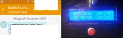
While the views of some of the conditions in Table II can be seen in Figure 10 to Figure 12.
1. Time: 18:00:00
MMCCk ,*N<ιr∙
PewertiTuan 1 BK. ⅛mw i suβanθ*< Mlt D
Fig. 10. Display condition at HP and LCD when SMS received in 18:00:00
2. Time: 23:00:00
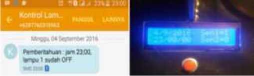
Fig. 11. Display condition at HP and LCD when SMS received in 23:00:00
3. Time: 06:00:00
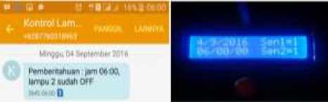
Fig. 12. Display condition at HP and LCD when SMS received in 06:00:00
The test results of Table 2 resulted in that the lamp1 and lamp2 can already turn ON and OFF according to plan based on input from the RTC. SMS sent to HP mobile has also been realized as planned, according to the ON OFF conditions of the light obtained from the condition into two photodiodes
[9] ITead Studio. (2011). Datasheet IComSat v1.1-SIM900
GSM / GPRS Shield. Available:
http://imall.iteadstudio.com/ im120417009.html
-
IV. CONCLUSION
The conclusion of this study are as follows: Supporting components of ON and OFF control equipment lighting utilizing microcontroller can be realized and are functioning in accordance with the plan. Both lights can already turn ON and OFF based on the input time of the RTC (the default) and the ON and OFF status can be checked with the SMS. Both lights also can be turn ON and OFF by SMS messages sent from and received by the mobile HP and microcontroller (IComSat) and feedback light conditions is already accepted by mobile HP corresponds to the ON and OFF actual of lighting.
ACKNOWLEDGEMENT
Acknowledgement to the Faculty of Engineering and the Institute for Research and Community Service UNUD to the funds provided so that this research can be carried out well.
References
-
[1] Huda, Nurul. (2015). Sstem lighting control based Short Message Service (SMS) Using Microcontroller AT89S51. Pelita Information Budi Darma, Volume: IX, Number 2, March 2015. Page 116-121.
-
[2] Putra,Agus Tiana. IGAP Agung Raka, Setiawan IN. (2013). Realization of Device Controller on-off Lamp Illumination via SMS (short message service) with Feedback Based Microcontroller AT89S52. MITE Vol.12 No. 1, 2013. Page 4 -10.
-
[3] Masinambow Vidy, Najoan Meicsy EI, Lumenta Arie SM. (2014). The switch controlling electricity through Android smart phone. e-journal Electrical and Computer Engineering. P. 1-9.
-
[4] Fadhil Muhammad, Bambang Dwi Argo, Lawrence Joseph. (2015). Prototype Design Tool Automatic Sprinklers with DS1307 RTC Timer System Based Microcontroller ATmega16 on Plant Aeroponics. Journal of Tropical Agriculture and Biosystems Engineering Vol. 3 No. 1.2015. P. 37-43.
-
[5] Sadeque Reza Khan, Ferdousi Arifa, Reza Khan Siddique. (2013). Real Time Generator Fuel level Meter Embedded with Ultrasound Measurement Sensors and Data Acquisition System. Journal of Automation and Control Engineering Vol. 1, No. 4, 2013 p. 343-348.
-
[6] Maxim. (2013). Data Sheet DS1307. available:
http://datasheets.maxim-ic.com/en/ds/DS 1307. pdf,
-
[7] Arduino. (2015) available: http://www.arduino.cc
-
[8] Vishay. (2002). 4x20 LCD Datasheet. Available:
http://pdf1.alldatasheet.com/datasheet.pdf/view/251984/ VISHAY/LCD-020M004A.html.
28
Discussion and feedback