Design and Development Automatic Fish Feed Measuring and Feeding System Based on Internet of Things
on
JURNAL ILMIAH MERPATI VOL. 11, NO. 2 AUGUST 2023
p-ISSN: 2252-3006
e-ISSN: 2685-2411
Design and Development Automatic Fish Feed Measuring and Feeding System Based on Internet of Things
Komang Martadana Wijayaa1, I Nyoman Piarsaa2, Putu Wira Buanaa3
aInformation Technology Department, Udayana University, Indonesia e-mail: 1komangmarta25@gmail.com, 2manpits@unud.ac.id, 3wb@unud.ac.id
Abstrak
Studi ini berfokus pada perancangan dan implementasi sistem pemberian makan ikan otomatis berbasis IoT menggunakan komponen-komponen penting seperti mikrokontroler ESP32, sensor RTC, sensor ultrasonik, sensor tegangan, motor stepper 5V, layar LCD, motor DC, dan relay. Tujuan utamanya adalah meningkatkan efisiensi pemberian makan ikan. Hasil penelitian mengungkap bahwa sistem ini berhasil menggabungkan dan mengelola proses dosis dan pemberian makan dengan tingkat keberhasilan 70%. Tingkat kesalahan yang diamati adalah 1,36% untuk sensor tegangan dan 1,33% untuk sensor ultrasonik. Secara khusus, baterai mengalami degradasi rata-rata sebesar 0,19V per jam operasional. Namun, tantangan yang dihadapi meliputi ketergantungan pada konektivitas Wi-Fi, kapasitas baterai yang tidak memadai, dan keterbatasan motor stepper untuk presisi dosis. Untuk peningkatan lebih lanjut di masa depan dengan penyertaan konektivitas Bluetooth, peningkatan kapasitas baterai (minimal 5,6Ah), dan penggunaan motor stepper 12V atau lebih tinggi untuk meningkatkan torsi dan akurasi.
Kata kunci: Internet of Things (IoT), mikrokontroler ESP32, Sistem otomatis penakaran dan pemberian pakan ikan, Sensor RTC
Abstract
This study focuses on design and implementationan IoT-based automatic fish feeding system using integral components like the ESP32 microcontroller, RTC sensor, ultrasonic sensor, voltage sensor, 5V stepper motor, LCD, DC motor, and relay. The primary objective is to enhance the efficiency of fish feeding. Results reveal that the system effectively amalgamates and manages the dosing and feeding processes with a 70% success rate. The observed error rates stand at 1.36% for voltage sensors and 1.33% for ultrasonic sensors. Notably, the battery experiences an average degradation of 0.19V per operational hour. However, challenges encompass dependencies on Wi-Fi connectivity, inadequate battery capacity, and limitations of stepper motors for dosing precision. For further upgrades in the future with the inclusion of Bluetooth connectivity, increased battery capacity (5.6Ah minimum), and use of 12V or higher stepper motors for increased torque and accuracy.
Keywords : Internet of Things (IoT), ESP32 microcontroller, Fish dosing and feeding automatic system, RTC Sensor
Internet of Things (IoT) products are commonly found in electronic devices and household appliances nowadays. IoT is a concept where objects can automatically send data to the internet without human intervention [1]. With the advent of wireless technology, Micro Electro Mechanical Systems (MEMS), the internet, and Quick Response (QR) codes, IoT has rapidly advanced. IoT encompasses objects used in data transmission processes, commonly used in daily life. It can enable controlling homes or furniture from mobile phones, detecting potential hazards like traffic and alerting users, thereby enhancing security and personal protection. IoT is not a single device or system but a combination of various devices working together. IoT devices essentially consist of four main components: sensors, connectivity, data
processing, and the User Interface (UI). IoT finds applications in numerous fields, including agriculture, healthcare, automotive, and livestock farming. In livestock farming, IoT plays a crucial role in easing the burden on livestock owners, particularly concerning the selection of good breeds, maintaining clean environmental conditions in the pens, and providing sufficient feed.
One common issue in livestock farming is inefficient and poorly controlled feeding. This can lead to problems like overfeeding or underfeeding, impacting the fish's quality and productivity [2]. Timely and accurate feeding is crucial for livestock farming, especially for fish farming. Delayed feeding resulting in inadequate food intake can affect the fish's value, quality, and selling price. Conversely, excessive feeding can lead to waste and the release of harmful substances into the water. IoT automation can address these issues and assist farmers in managing their farms efficiently, freeing up time spent on feeding for other farm activities. While not all livestock sectors can implement automated feeding due to varying feed forms and compositions, fish farming can benefit from IoT automation since fish feed, such as pellets, is uniform and easy to dispense.
Hence, a system is needed to aid farmers in addressing this problem. The research on "Design and Development Automatic Fish Feed Measuring and Feeding System Based on Internet of Things" was conducted to offer a solution for automating fish feeding in the farming sector. An IoT device was developed using the ESP32 microcontroller as the control chip, comprising a feed dispenser connected to the ESP32 and a smartphone application acting as the interface between the farmer and the device. The implementation of the IoT-based automated fish feeding system allows for remote control and monitoring. With this system, fish feeding and monitoring can be done automatically, and users can track the total feed dispensed through the application on their smartphones, eliminating the need for manual intervention. This IoT system is expected to optimize the time spent by fish farmers.
There is a similar previous research titled "Remote Control System for Feeding Catfish using Internet of Things (IoT) Technology" by Dwi Herliabriyana [3], which aimed to utilize the Internet of Things to provide controlled feeding for catfish remotely, achieving efficiency in the amount and timing of feeding. The research employed a servo motor to open and close the feeding device, controlled by an Arduino Uno and connected to the internet through an internet shield. A DC motor was used to propel the feed during feeding action when the motor was activated. The main difference between the previous research and the current study lies in the equipment used. The previous research relied on time-based control for the servo motor, while the current study used a mechanical mechanism designed with a stepper motor. Additionally, the previous research employed a web-based approach, whereas the current study utilized a mobile application for control.
This research serves as an alternative solution for fish farming, utilizing IoT-based technology to automate fish feeding, control, and monitoring, benefiting the community in the fish farming process.
The method used in this research is the Research and Development (R&D) method. Research and development method is a research approach employed to create specific products and test the effectiveness of these products [4]. Research and Development (R&D) is a process used to develop new products, technologies, or systems through a series of structured stages. These stages include planning, implementation, and evaluation stages. The planning stage in the R&D method is the first stage of the research and development process. In this stage, researchers identify the problem to be studied and develop a plan to address the problem. The implementation stage in the R&D method is the second stage of the research and development process. In this stage, researchers collect data and use appropriate analysis techniques to process the data. The evaluation stage in the R&D method is the third stage of the research and development process. In this stage, researchers assess the research results and determine whether the research objectives have been achieved.

Figure 1. Research Flow
Figure 1 depicts the flowchart diagram of the research on designing an Internet of Things-based automatic fish feeding and dispensing system. The study begins with a thorough literature review of fish feeding devices and similar technologies from books and online journals. Next, the device requirements are analyzed to determine its functionalities and the necessary electronic components. The design phase involves creating the overall device layout, including its form and electronic composition. Testing is then conducted to assess the device's functionality, and data from the tests are collected and analyzed to draw conclusions.
Modeling includes a general description of the system, this is very important to understand the operational logic that has been designed and ensure that the system functions according to the specified requirements. The general description explains the overall conceptual description of the research. The general description of the system in research can be seen in the figure 2.
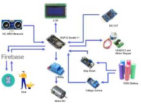
Figure 2 General Description System
Figure 2 is an overview of the automatic fish feed measuring and feeding system. The system uses the ESP32 DevKit V1 microcontroller as the system controller. The sensors used include the HC-SR04 ultrasonic sensor which is used to determine the height of the amount of feed available in the food storage tube. The DS1307 Real Time Clock (RTC) sensor is used to obtain the current time for the system to be used as feeding time. Voltage sensor is used to monitor the battery voltage. ULN2003 Driver drive the stepper motor which is used to rotate the mechanical mechanism to measure the feed according to the previously programmed dose. The relay is used as an automatic switch to turn on the DC motor which functions as a drive for the feed spreader mechanism. The LCD is used to display the current time, next feeding schedule, remaining feed in storage, and battery voltage. The 18650 battery serves as the power provider for the entire system. Data from the device is then sent to the Firebase database so that it can be monitored remotely using the internet.
The system flowchart is expected to aid in visually communicating information about the system, facilitating system development or maintenance. The system flowchart can be seen in the figure 3.
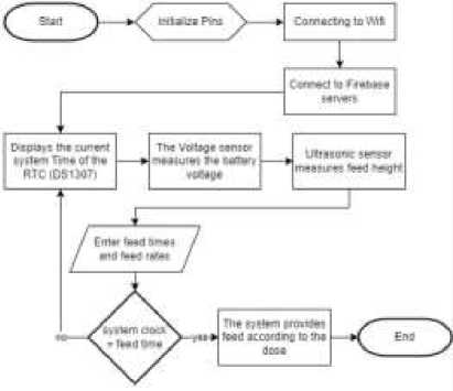
Figure 3 Flowchart System
Figure 3 shows the flowchart of the system being developed. The system begins with pin initialization to load all required libraries. Next, the ESP32 initiates the connection to the network using the provided SSID and password to connect to the Firebase server. The system obtains the current time from the RTC sensor (DS1307), battery voltage from the voltage sensor, and the availability of fish feed from the feed height calculation. The user can set the feeding schedule and portion by inputting the feeding time and feed quantity into the system. When the inputted feeding time matches the system's time, the automatic feeding will be carried out according to the predetermined feed portion.
The Device Design illustrates the mechanism of the automatic fish feeding and dispensing system. The design image was created using the Fusion 360 application. The design can be viewed in Figure 4 and 5.
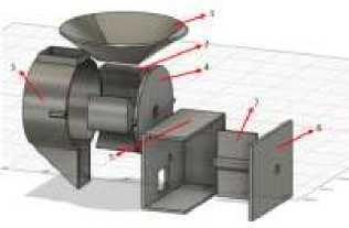
Figure 4 Dosing Mechanism
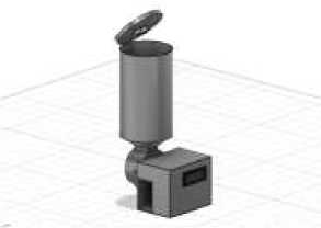
Figure 5 Device Design
Figure 4 and 5 is the dosing mechanism design and device design of the feeding and dispensing system mechanism. The dimensions of the mechanical design are 16cm in length, 10cm in width, and 20cm in height, excluding the adjustable storage tube height as needed, with an estimated weight of 600g.
The circuit schematic is an illustrative representation of the electronic components' arrangement that will be used in the system. The circuit schematic overview can be seen in Figure 5.
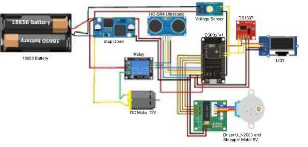
Figure 6 Circuit Schematic
Figure 6 shows the overall circuit schematic of the system to be built. The hardware used is the device described in the general description of the system. All sensors are connected to the microcontroller and confirmed to be connected to battery power
A literature review is a crucial phase in research, involving the search and examination of various written materials such as books, journals, articles, and other sources of information relevant to the subject under investigation. This process aids in gaining a deeper understanding of existing knowledge in a specific field and identifying prior research that is pertinent to the subject being studied.
Internet of Things (IoT) is a concept where all internet-connected devices have the ability to communicate and exchange data with each other. This enables these devices to work automatically and interconnect, enhancing efficiency and providing more effective problemsolving solutions. For example, a smart home connected to the IoT could have lights that automatically turn on and off according to needs, or a washing machine that can be set to operate when electricity at home is cheapest. IoT can also be used in fields such as healthcare, agriculture, transportation, and many others to help solve various problems and improve efficiency. By integrating internet-connected devices, IoT can make our lives easier and more efficient [5].
A microcontroller is a small chip or electronic device that functions as a controller for electronic systems. Microcontrollers have a CPU, memory, and input/output devices that can be used to run programs and control other electronic devices [6]. Popular examples of microcontrollers include Arduino, Raspberry Pi, ESP8266, ESP32, and PIC. Microcontrollers are often used to create Internet of Things (IoT) applications, robotics, control systems, and various other electronic devices.
A sensor is a device that detects and measures physical properties or changes in the environment and converts them into electrical signals or data for further processing or analysis [7]. DS1307 is a module that contains a Real-Time Clock (RTC) sensor. The DS1307 module can be used to measure time and date with high accuracy [8]. HC-SR04 is an ultrasonic sensor that can be used to detect the distance and speed of objects. This sensor works by transmitting ultrasonic signals and measuring the time it takes for the signal to return after hitting an object [9]. The Arduino voltage sensor is a sensor used to measure electrical voltage in the range of 0-25V [10]. The 5V 28BYJ-48 Stepper Motor is a stepper motor with an operating voltage of 5V and a coil diameter of 28 mm. This motor belongs to the family of unipolar stepper motors, which has four poles and uses a bidirectional driver to control its rotational movement [11]. LCD (Liquid Crystal Display) which is a technology used to create visual display screens. LCDs are commonly used in electronic devices such as televisions, computers, mobile phones, and
others. This technology utilizes liquid crystals that can transform light into images visible to the human eye [12] .
Arduino IDE is an Integrated Development Environment (IDE) or software used to program and test Arduino devices. Arduino IDE features a user-friendly interface and provides various functionalities such as code editing, compiling, and debugging, making the application development process for Arduino devices more convenient [13]. It also offers numerous libraries and features that assist in creating more interactive and complex applications.
Firebase is a platform developed by Google that offers a variety of services and features for building mobile and web applications [14]. Firebase provides several useful features for app developers, including data storage, user authentication, notification sending, and more. Firebase enables developers to easily and quickly integrate these features into their applications without the need to build a backend from scratch.
This section contains the results and discussion of research such as the realization of hardware design results, software design results, test results and analysis of test results.
The results of the hardware design of the automatic fish feed measuring and feeding system can be seen in Figures 7 to 13.
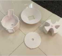
Figure 7 3D Model Print Results
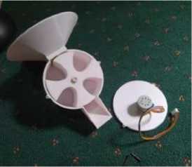
Figure 8 Mechanism of Dosing
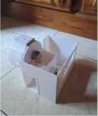
Figure 9 Main Body and Ejector
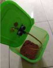
Figure 10 Installation of Ultrasonic Sensors
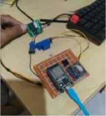
Figure 11 Circuit Schematic Implementation
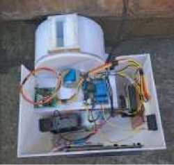
Figure 12 Installation of Electronic Devices
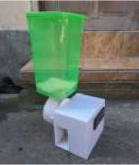
Figure 13 Hardware Design Results
Figures 7 to 13 are the results of the hardware assembly of each component that has been prepared beforehand. The hardware will then be programmed to be able to run the system so that the device can be used.
The Android operating system was chosen as the application development platform with consideration of the convenience offered by its open nature. The following is the process of making an Android application from the design results for an automatic fish dosing and feeding system.
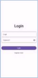
Figure 14 Monitoring and Control Application
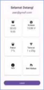
Figure 14 is the result of the monitoring and controlling application design. There is information on the dashboard, namely hours of feeding, device battery voltage, amount of remaining feed, feed dosage, information related to the application, and a check button to do a brief test of the tool.
The realtime database has a reference url that is used as the database address, it is important to know this url before it will be used to connect devices [15]. The next process is to create a root which will later contain the keys and values used to store variable values.
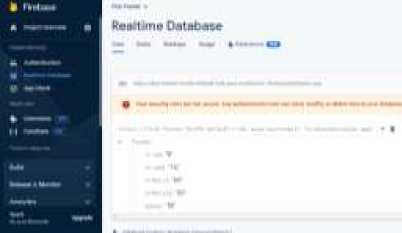
Figure 15 Database Setting
Figure 15 is the result of Google Firebase's realtime database service settings. Firebase detected a device named Feeder which has 5 variables sent by ESP32 namely ArJam, ArJam2, ArMinit, ArMinit2, feed, spin and voltage. ArJam, ArJam2, ArMenit, ArMenit2 variable values can be changed on firebase to send to ESP32 as an alarm for feeding. Makan and voltage variables are the resulting variables from ultrasonic sensor readings to find out what percentage of feed availability and voltage sensor readings to determine battery voltage. The Spin variable is a variable that can be entered to determine how many doses to make when feeding.
System testing on the Internet of Things device was conducted to verify that each component within the research functions as intended. The following presents the results of the system monitoring and device control testing.
The results of sensor readings and sensor calibration can be seen in table 1 and 2 of the voltage sensor test results.
Table 1 Voltage Sensor Test Results Table 2 Ultrasonic Sensor Test Results
|
No |
Sensors |
Voltage Multimeter |
Error(%) |
No |
Sensors |
Distance (Cm) Ruler |
Error(%) |
|
1 |
12.20 |
12.36 |
1.29 |
1 |
4.12 |
4.22 |
2.37 |
|
2 |
12.12 |
12.34 |
1.78 |
2 |
4.26 |
4.34 |
1.84 |
|
3 |
12.08 |
12.29 |
1.71 |
3 |
4.28 |
4.31 |
0.70 |
|
4 |
12.05 |
12.26 |
1.71 |
4 |
5.63 |
5.72 |
1.57 |
|
5 |
12.04 |
12.18 |
1.15 |
5 |
6.47 |
6.6 |
1.97 |
|
6 |
11.99 |
12.09 |
0.83 |
6 |
7.34 |
7.46 |
1.61 |
|
7 |
11.67 |
11.88 |
1.77 |
7 |
7.36 |
7.46 |
1.34 |
|
8 |
11.61 |
11.84 |
1.94 |
8 |
7.41 |
7.59 |
2.37 |
|
9 |
11.48 |
11.57 |
0.78 |
9 |
8.44 |
8.58 |
1.63 |
|
10 |
11.36 |
11.55 |
1.65 |
10 |
8.59 |
8.68 |
1.04 |
|
11 |
11.26 |
11.45 |
1.66 |
11 |
11.71 |
11.68 |
0.26 |
|
12 |
11.15 |
11.27 |
1.06 |
12 |
12.4 |
12.47 |
0.56 |
|
13 |
11.13 |
11.26 |
1.15 |
13 |
13.07 |
13.17 |
0.76 |
|
14 |
11.10 |
11.22 |
1.07 |
14 |
13.37 |
13.51 |
1.04 |
|
15 |
11.01 |
11.11 |
0.90 |
15 |
13.66 |
13.78 |
0.87 |
|
Error Rate |
1.36% |
Error Rate |
1.33 | ||||
Table 1 and 2 is the test result of the battery voltage monitoring function and ultrasonic sensor test result. From the results obtained, it shows that the sensor reading is smaller than the value obtained by the multimeter, but the difference in the sensor reading value is still relatively small when viewed from the average error value.
The results of the control function are the results of testing by control using android application then running the IoT system with a certain test scheme in accordance with the control system being tested. The control system tested is the control function of feeding time, feed dosage control and manual feeding control.
Table 3 Feeding Time Control Test Results
|
No |
Condition |
Expected Results |
Test Number |
Status |
|
1 |
The user sets the |
The feeding time on the system |
1 |
Valid |
|
feeding time |
changes according to the input |
2 |
Valid | |
|
from the user |
3 |
Valid | ||
|
4 |
Valid | |||
|
5 |
Valid | |||
|
6 |
Valid | |||
|
7 |
Valid | |||
|
8 |
Valid | |||
|
9 |
Valid | |||
|
10 |
Valid | |||
|
Table 4 Feed Dosing Control Test results | ||||
|
No |
Condition |
Expected Results |
Test Number |
Status |
|
1 |
The user adjusts |
The dosage of feeding in the |
1 |
Valid |
|
the dosage of |
system changes according to the |
2 |
Valid | |
|
feeding |
input from the user |
3 |
Valid | |
|
4 |
Valid | |||
|
5 |
Valid | |||
|
6 |
Valid | |||
|
7 |
Valid | |||
|
8 |
Valid | |||
|
9 |
Valid | |||
|
10 |
Valid | |||
Table 5 Manual Feeding Test Results
|
No Condition |
Expected Results Test Number Status |
|
1 The user initiates feeding manually by pressing the "Feed" button in the application |
The application sends 1 Valid commands to the database to 2 Valid run the feed on the IoT device 3 Valid 4 Valid 5 Valid 6 Valid 7 Valid 8 Valid 9 Valid 10 Valid |
Notifications are used to provide information to the user such as feed that is about to run out, battery power is starting to decrease and the status of the device is feeding.
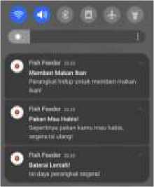
Figure 16 Notification
Figure 16 is an image of the result of a notification from an Android application that will appear when the notification conditions are met. A feed notification will appear when the feed condition is less than 30% in storage, a low battery voltage notification will appear when the voltage is less than 11.3V and a feeding notification when the feeding status is “on”.
System implementation testing is focused on system performance to carry out the dosing and feeding function automatically whether it can run perfectly or not.
Table 6 System Automation Test Results
|
No |
Condition |
Expected Results |
Test Number |
Status |
|
1 |
The system runs dosing |
The system can work |
1 |
Valid |
|
and feeding automatically |
according to the system |
2 |
Valid | |
|
according to the specified |
designed |
3 |
Valid | |
|
time |
4 |
Valid | ||
|
5 |
Invalid | |||
|
6 |
Invalid | |||
|
7 |
Valid | |||
|
8 |
Valid | |||
|
9 |
Valid | |||
|
10 |
Invalid |
Table 6 is the result of testing the entire automatic fish dosing and feeding system. The test results show that out of 10 times of testing, there are 7 valid results and 3 times invalid results. The system performs automatic dosing and feeding of fish. This shows that the designed system can only work with a percentage of 70% of the entire test. System failure was caused by a dosing mechanism that only used a 5V stepper motor which resulted in the stepper motor jamming and the torque generated was insufficient to rotate the measuring mechanism due to frictional resistance and not strong enough to split the food it was stuck on.
Table 7 Battery Resistance Test Results
|
Test Number |
Voltase(V) |
|
1 |
12.10 |
|
2 |
11.71 |
|
3 |
11.68 |
|
4 |
11.53 |
|
5 |
11.40 |
|
6 |
11.26 |
|
7 |
11.15 |
|
8 |
10.8 |
|
Average Voltage Drop |
0.19 |
Table 7 is the result of testing the battery power resistance. Based on the test results, it was found that the use of batteries in IoT devices experienced an average voltage drop of 0.19V every hour with a battery capacity of 800 mAh. Testing is carried out with a scenario of checking every 1 hour and operating the device for automatic administration twice. This shows that in such situations, IoT device batteries need to be monitored regularly and replaced to maintain optimal performance.
Table 8 Dosing Test Results
|
Test Number |
Measurement Results (g) |
|
1 |
23 |
|
2 |
19 |
|
3 |
25 |
|
4 |
20 |
|
5 |
21 |
|
6 |
19 |
|
7 |
24 |
|
8 |
22 |
|
9 |
25 |
|
10 |
24 |
|
11 |
22 |
|
12 |
24 |
|
13 |
18 |
|
14 |
22 |
|
15 |
25 |
|
Average Measurement Results(g) |
22.2 |
|
Error Rate |
12.62% |
Table 8 above is the result of testing the number of doses on IoT devices. The system is set to be able to do measurements with a total dose of 25 grams on the application. The results from the experiment showed that the lowest dose was 18 grams and the highest result was 25 grams from 15 experiments with an average value of 22.2 grams so that an error rate of 12.62% was obtained.
In conclusion, based on the conducted testing, the system's success rate for fish feeding and dispensing only reached 70%. The average error in voltage sensor readings was 1.36%, and the error rate in ultrasonic sensor readings was 1.33%. The average battery voltage drop was 0.19V per hour during system operation. The developed Android application successfully connected to the device's database server, enabling control over feeding schedule, portion, and manual feeding, as well as sending notifications for empty feed, low battery, and ongoing feeding. The system encountered challenges such as the requirement for Wi-Fi network connectivity for control and monitoring, insufficient battery life needing a bigger capacity and limitations of stepper motors for dosing precision. For future improvement, the device can be connected by Bluetooth connectivity, augmenting battery capacity (minimum 5.6Ah), and utilizing 12V or higher stepper motors to bolster torque and accuracy.
References
-
[1] A. El Hakim, “Internet of Things ( IoT ) System Architecture and Technologies,” White
Pap. v1.0, no. March, pp. 0–5, 2018, doi: 10.13140/RG.2.2.17046.19521.
-
[2] U. Faruq, R. Jumadi, and M. S. Dadiono, “PENGARUH FREKUENSI PEMBERIAN
PAKAN YANG BERBEDA TERHADAP PERTUMBUHAN IKAN BANDENG (Chanos chanos),” J. Perikan. Pantura, vol. 2, no. 1, p. 10, 2019, doi: 10.30587/jpp.v2i1.806.
-
[3] D. Herliabriyana, S. Kirono, and H. Handaru, “Sistem Kontrol Pakan Ikan Lele Jarak
Jauh Menggunakan Teknologi Internet of Things(IoT),” J. Ilm. Intech Inf. Technol. J. UMUS, vol. 1, no. 02, pp. 62–74, 2019, doi: 10.46772/intech.v1i02.70.
-
[4] S. Haryati, “Research And Development( R & D ) Sebagai Salah Satu Model Penelitian
Dalam,” Academia, vol. 37, no. 1, p. 13, 2012.
-
[5] P. Prasetyawan, S. Samsugi, and R. Prabowo, “Internet of Thing Menggunakan
Firebase dan Nodemcu untuk Helm Pintar,” J. ELTIKOM, vol. 5, no. 1, pp. 32-39, 2021, doi: 10.31961/eltikom.v5i1.239.
-
[6] A. B. Putranto, Z. Muhlisin, A. Lutfiah, F. Mangkusasmito, and M. Hersaputri,
“Perancangan Alat Karakterisasi Dioda dengan ESP32 dan Rangkaian Op-Amp LM358 Berbasis Android,” Ultim. Comput. J. Sist. Komput., vol. 13, no. 1, pp. 22-29, 2021, doi: 10.31937/sk.v13i1.2088.
-
[7] R. Rajesh, “The Analysis of Different Types of IoT Sensors and security trend as
Quantum chip for Smart City Management,” Stphilos.Ac.in, vol. 20, no. January, pp. 5560, 2018, doi: 10.9790/487X-2001045560.
-
[8] S. M. Sutan, D. Kadarisman, S. Hosni, and F. Fadlillah, “Rancang Bangun Sistem Irigasi
dan Pemberian Nutrisi Otomatis Berbasis Rtc ( Real Time Clock ) pada Sistem Hidroponik Nutrien Film Technique ( Nft ) Rrigation System Architecture And The Granting Of Nutrition-Based Automatic RTC ( Real Time Clock ) On The,” J. Keteknikan Pertan. Trop. dan Biosist., vol. 5, no. 3, pp. 117-128, 2017, [Online]. Available:
https://www.jkptb.ub.ac.id/index.php/jkptb/article/view/408
-
[9] I. W. A. W. K. Heru Purwanto, Malik Riyadi, Destiana Windi Widi Astuti, “Komparasi
Sensor Ultrasonik HC-SR04 Dan JSN-SR04T Untuk Apikasi Sistem Deteksi Ketinggian Air,” J. SIMETRIS, vol. 10, no. 2, pp. 717-724, 2019.
-
[10] Electrical4U, “Voltage and turn ratio test of Transformer,” 2020. https://www.electrical4u.com/voltage-and-turn-ratio-test-of-transformer/ (accessed Aug. 26, 2023).
-
[11] E. Yilmazlar, V. Erdemir, H. Kuscu, A. Gullu, E. Yilmazlar, and H. Ku§?u, “Design Of Stepper Motor Control Interface With Embedded Systems A iNCELEME SURDURULEBiLiR TARIM POLiTiKALARI ANKETi View project Object Tracking by PID Control and Image Processing On Embedded System View project Design Of Stepper Motor Control Interface ,” Int. J. Eng. Res. Dev., vol. 14, no. 6, pp. 17-22, 2018, [Online]. Available: www.ijerd.com
-
[12] A. H. Rahmat Tullah, Sutarman, “Sistem Penyiraman Tanaman Otomatis Berbasis Mikrokontroler Arduino Uno Pada Toko Tanaman Hias Yopi,” J. Sisfotek Glob., vol. 9, no. 1, pp. 2088-1762, 2019, [Online]. Available:
https://www.journal.global.ac.id/index.php/sisfotek/article/view/219/229
-
[13] M. Fezari and A. A. D. Al Zaytoona, “Integrated Development Environment ‘IDE’ For Arduino Integrated Development Environment ‘IDE’ For Arduino Introduction to Arduino IDE,” ResearchGate, no. October, 2018, [Online]. Available:
https://www.researchgate.net/publication/328615543
-
[14] R. J. Gunadi, R. Tanone, and Y. R. Beeh, “PENERAPAN FIREBASE CLOUD STORAGE PADA APLIKASI MOBILE ANDROID UNTUK MELAKUKAN PENYIMPANAN IMAGE LAHAN PERTANIAN,” vol. 4, no. 2, pp. 282-291, 2020, doi:
https://doi.org/10.36294/jurti.v4i2.1668.
-
[15] M. A. Mokar, S. O. Fageeri, and S. E. Fattoh, “Using Firebase Cloud Messaging to Control Mobile Applications,” in 2019 International Conference on Computer, Control, Electrical, and Electronics Engineering (ICCCEEE), 2019, pp. 1-5. doi:
10.1109/ICCCEEE46830.2019.9071008.
Design and Development Automatic Fish Feed Measuring and Feeding System Based on 126
Internet of Things (Komang Martadana Wijaya)
Discussion and feedback