Propeller Speed Control System on Autonomous Quadcopter with Variations in Load Fulcrum Point
on
LONTAR KOMPUTER VOL. 12, NO. 3 DECEMBER 2021
DOI : 10.24843/LKJITI.2021.v12.i03.p04
Accredited Sinta 2 by RISTEKDIKTI Decree No. 30/E/KPT/2018
p-ISSN 2088-1541
e-ISSN 2541-5832
Propeller Speed Control System on Autonomous Quadcopter with Variations in Load Fulcrum Point
Ratna Aisuwaryaa1, Ibrahim Saputraa2, Dodon Yendria3
aComputer Engineering, Faculty of Information Technology, Andalas University Kampus Unand Limau Manis, Padang, Indonesia 1aisuwarya@it.unand.ac.id
Abstract
The need for unmanned vehicles is increasingly needed in certain conditions, such as distribution of disaster supply, distribution of medicines, distribution of vaccines in the affected areas in pandemic situations. The various types of goods to be distributed require a different fulcrum. This research implemented PID control for the quadcopter balance control system to achieve stability during hovering. PID control is used to achieve a certain setpoint to produce the required PWM output for the propeller to reach a speed that can fly the quadcopter tilted until it reaches a steadystate. Tests were carried out on the roll and pitch motion of the quadcopter by providing a load. The results show that PID control can be implemented for the quadcopter balance control system during hovering by determining the PID constants for each roll and pitch motion with Kp = 0.15, Kd = 0.108, and Ki = 0.05. The quadcopter takes 3 – 6 seconds to return to the 0-degree setpoint when it is loaded.
Keywords: Quadcopter, stability, PID, speed control, fulcrum
This aerial explorer robot is often referred to as an Unmanned Aerial Vehicle (UAV). One type of UAV that is widely used is the quadcopter. Quadcopter has many potential uses that can be developed, one of which is the transportation of goods. The need for unmanned vehicles is increasingly needed in certain conditions, such as distribution of disaster supply, distribution of medicines, distribution of vaccines in the affected areas in pandemic situations. The various types of goods to be distributed require a different fulcrum. For the transportation of goods, the mass and the fulcrum of the load affect the rotational speed of the propeller motor, which affects the quadcopter's stability. The modeling and practical control design of a UAV based on a quadcopter have been conducted in several studies. The PID controllers were set for angular position stability (roll and pitch) and yaw speed [1]. In the field of surveillance and remote package delivering systems also developed using microcontrollers that are programmed to turn on the quadrotors using electronic speed controllers and power electronics design considerations[2][3]. Modeling and simulation of multi-rotors using Spatial Operator Algebra are useful for a minimal range of angles[4]. Quadcopter flight stability is achieved when all propellers generate equal thrust in hover and throttle mode [5]. A workbench prototype testing on a breadboard is important to get initial setups for testing results[6][7].
Research [8] shows the implementation of UAVs in the agriculture field to spray herbicides. Thus, the stability of a quadcopter flight control for the intended load and various conditions is crucial. The quadcopter model must have parameters on various relationships, including propeller thrust torque, thrust-PWM, and thrust-angular speed to a certain level of accuracy [9][10]. Various control algorithms have been developed to stabilize the quadcopter over a certain trajectory since it is hard to follow a particular trajectory. In paper [11], a fuzzy-PID controller is designed using MatLab. Low-level controller using robust control techniques also simulated in[12]. The dynamic model of the drones, the control method of the quadcopter unmanned aerial vehicle with four brushless DC motor speed control, is given in[13].
Furthermore, since the quadcopter will carry loads, a mathematical model of the dynamics of motion of a quadcopter is needed taking into account the important effect of the lifting rotors rotation speed change 14]. Our previous research [15] shows stability response in the quadcopter limited to the condition of the quadcopter hovering for pitch and roll angles. We also get the initial setup for the maximum load for different fulcrums; 950g for the fulcrum in the middle of the quadcopter, 580g for the load is placed 6 cm from the middle of the quadcopter, and 310g if the load is placed on one motor. So that in this research, a quadcopter was designed that is capable of carrying loads that have different variations in fulcrum and self-stabilizing automatically. PID control is used to achieve a certain setpoint to produce the required PWM output for the propeller to reach a speed that can fly the quadcopter tilted until it reaches a steady-state. Tests were carried out on the roll and pitch motion of the quadcopter by providing a load. This study aims to produce a quadcopter design that can fly stably and be balanced when the load is implemented at different fulcrum points.
Our research is based on an experimental project. It consists of a data reading process and PID control processing based on variations in load fulcrum. The system read the Quadcopter orientation sensor data after being loaded at a predetermined point using the MPU-9250 orientation sensor on the Ardupilot. Then, PID control processing is based on a set point. The PID control processes the data sent from the sensor. The output is a PWM signal used to control the motor to achieve predetermined quadcopter balance points.
In three-dimensional space, the quadcopter has two coordinate systems Figure 1) : (1). body frame; coordinates that move together with the quadcopter, and (2) inertial frames; quadcopter's coordinates reference points. The inertial frame or setpoints work as reference balance for the quadcopter.

X inertial frame
Figure 1. Quadcopter Body frame and Inertial Frame
Rotational matrix mathematical models are used to change the quadcopter's movements to match the inertial value of the frame (equation 1).
c(θ)c(ψ) c(θ)s(ψ) -s(θ)
Cbvi= l(-c(Φ)s(ψ)+s(φ)s(θ)c(ψ)) (c(φ)c(ψ)+s(φ)s(θ)s(ψ)) s(φ)c(θ)
(1)
(s(φ)s(ψ)+c(φ)s(θ)c(ψ)) (-s(φ)c(ψ)+c(φ)s(θ)s(ψ)) c(φ)c(θ)
Where, Cbvi is the conversion of the body frame value to the inertial frame, φ(phi),θ(theta),ψ(psi) is a rotational angle formed by the quadcopter when flying against x, y, z axes.
The inertia matrix describes the moment of inertia contained in the quadcopter on each axis.
Jb
Jxx 0 0
= 0 Jyy 0
0 0 Jzz
(2)
Where Jbis quadcopter inertia in body frame, Jxx,Jyy,Jzz is the quadcopter moment of inertia to each axis.
Motor lift or thrust determines the ability of a quadcopter to fly, calculated by:
T = CTρArr2ϖ2
(3)
Where T is the thrust of the motor, CT is the coefficient of thrust in each motor. ρ is the mass density, Ar is the propeller rotation area, r is the radius of the rotor, and ϖ2 is the angular velocity of the rotor.
The body frame also accepts a lift from the rotor. The lift will only affect the Z-axis, so the formula for lift is:
0
b
FA,T =
0
cT(ϖ12 + ϖ22 + ϖ32 + ϖ42)
(4)
The equation for finding a motor RPM is useful for converting PID control output with the following formula:
RPM = (Throttle%)cR + b
(5)
Where cR is Motor RPM constant per input voltage, and b is resistance on the y-axis.
The speed control system model is built in the Simulink module of MATLAB. Using the mathematical model described previously, the variables of each pitch angle, roll, and yaw quadcopter can be determined. Furthermore, we design a quadcopter speed control system divided into several function blocks, as shown in Figure 2.
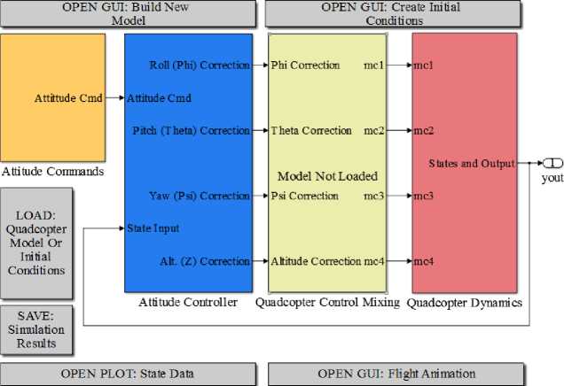
Figure 2. Block diagram of a Quadcopter control system simulation
In the Attitude Commands block, the data set point for each roll, pitch, yaw, and quadcopter height can be determined as an input of the desired quadcopter condition, then in the Attitude Controller block a PID control data processing for each roll, pitch, yaw and the height of the quadcopter can be seen in Figure 3.
Attitude
Cnid
State Input
|
<Phi> | |
|
---► | |
|
<Γbe> | |
|
<Q> |
|
Attitude Command | ||
|
Phi State |
⅛ |
Phi |
|
Ki |
Correction | |
|
P State |
Kd | |
Roll (Phi) Control
Roll (Phi) Correction
|
Attitude Command Theta State ∣f Theta QState Kd Correction |
Picth (Theta) Collection |
Pitch (Theta) Control
Figure 3. Attitude Control Process Diagram of each motion and height of the quadcopter
As seen in Figure 3, each roll and pitch motion uses two input feedback: the angular acceleration and the Euler kinematic angle. By implementing the PID control, the correction in each motion and the quadcopter's height can be calculated to reach the given setpoint. The output of PID is in the form of power or throttle for each motor that affects the motion of roll, pitch, and quadcopter height.
Then the correction of each motion is processed in the quadcopter control block, the throttle for each motor can be determined. Finally, in the quadcopter dynamic block, the throttle of each motor is converted to RPM by using equation 5, and quadcopter attribute data can be determined in the simulation by implementing equations 1-4.
The PID constant value that has been obtained is implemented on the designed quadcopter. The quadcopter is turned on and flown in a hover condition, without any load. The expected outcome of this test is that the quadcopter can reach and stabilize at setpoints of 0 degrees after applying load at the time of hover.
The following test scenario for this test item :
-
a. Load: Weights 700 g, 500 g, and 200 g are given to the quadcopter with a fulcrum variation in the middle point between 2 arms and placed on one quadcopter arm.
-
b. Evaluation: The quadcopter's performance is compared to the simulation to get the percentage of errors to be analyzed.
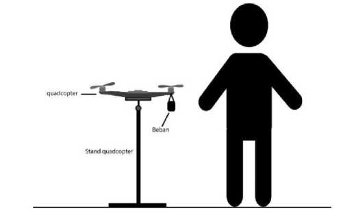
Figure 4. Load Test Illustration
In this section, hardware testing determines that the designed system works and produces output that matches the purpose. From this test, the obtained data will be used to analyze the work process of each hardware so that we can proceed to the test environment set up. The assembled quadcopter can be seen in Figure 5.
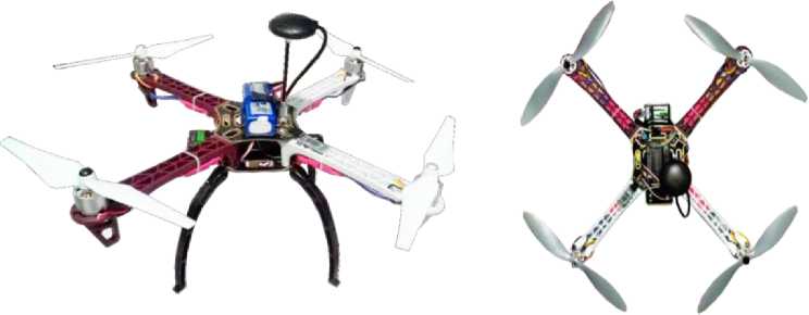
Figure 5. Quadcopter Top and Front View
The PID control data can be tested and determined using a quadcopter simulation on Matlab with this configuration. The first step in this test is inputting hardware data previously measured to be a model in the simulation, as shown in Figure 4.5.
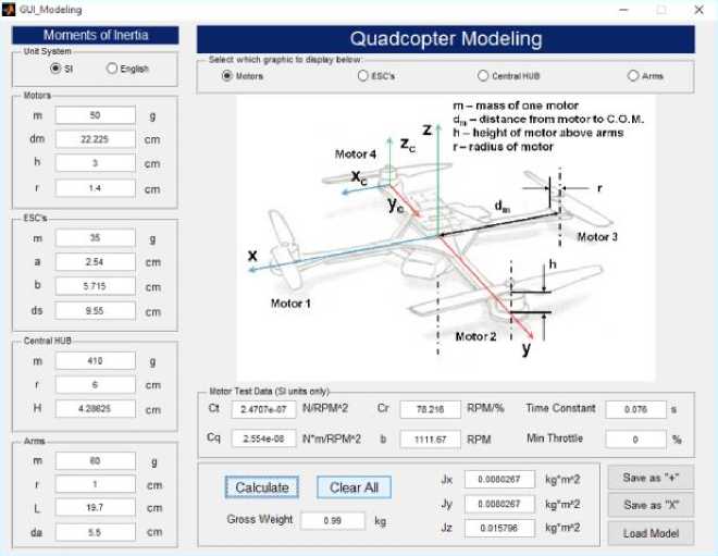
Figure 6. Quadcopter model simulation
From the results of the measurement of technical specification using the hardware data, we get the moment of inertia for each component and the total moment of inertia quadcopter as in Table 1 [15]:
Table 1. Moment of Inertia of Quadcopter [15]
|
Jx |
Jy |
Jz |
Unit | |
|
Motor |
0.005009 |
0.005009 |
0.009899 |
Kg.m2 |
|
ESC |
0.000661 |
0.000661 |
0.001322 |
Kg.m2 |
|
Arm |
0.002413 |
0.002413 |
0.00362 |
Kg.m2 |
|
Middle Frame |
0.000429 |
0.000429 |
0.000738 |
Kg.m2 |
|
Total Moment of Inertia |
0.008513 |
0.008513 |
0.015579 |
Kg.m2 |
After the model is obtained, hover conditions with slope disturbance and roll motion is simulated in Figure 7.
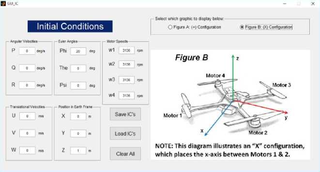
Figure 7. Hover condition simulation with 20-degree disturbance in roll motion
The next step is an experiment to determine the constant value of the PID control for each Eulerian motion, where at this stage, the PID test is only performed at a roll angle as follows first.
-
a. Stable Oscillating Roll (Figure 8.a): At this stage, Ku = 0.25 and Pu = 5.8 seconds using Ziegler-Nicholas theory for PID control, where Kp = 0.15, Ki = 0.051, and Kd = 0.108.
-
b. Stable Oscillating Pitch (Figure 8.b): Furthermore, the Pitch motion obtained Ku = 0.25 and obtained Pu = 5.8 seconds using Ziegler-Nicholas theory for PID control, where Kp = 0.15, Ki = 0.051, and Kd = 0.108.
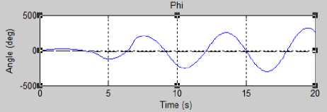
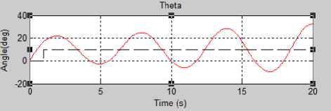
a.Roll
b.Pitch
Figure 8. Stable Oscillating Pitch and Roll
Simulation experiments were conducted to determine the PID constant for each roll and pitch motion. These experiments go through the same stage by increasing the Kp constant value until a stable overshoot is shown in Figure 9 10. Thus, Ku gain value and the Pu oscillation period value can be determined to get the values of Kp, Ki, and Kd using the Ziggler-Nicholas approach. The PID constant obtained for each roll and pitch motion is implemented in the testing process.
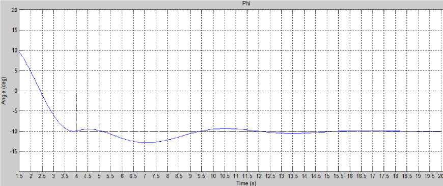
Figure 9. Roll Quadcopter Simulation with PID
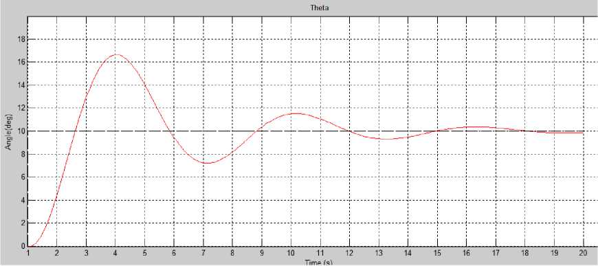
Figure 10. Pitch Quadcopter Simulation with PID
At this stage, the PID test is performed on the designed quadcopter (Figure 11). The response time of the quadcopter PID control is collected, where the data collection of each roll and pitch motion starts from the time of disturbance or error in the quadcopter. Data were analyzed in several parts, namely roll, pitch, and motor PWM, based on response time, as shown in Figures 12 and 13.
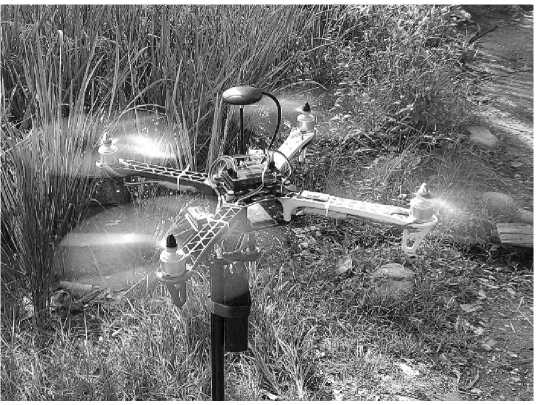
Figure 11. Pitch Quadcopter Simulation with PID
By using collected data, calculation of the response time control on the quadcopter was designed as follows (Figure 12):
Based on the calculation of the percent overshoot obtained a value of 20.20%, which means the quadcopter rotates at a pitch motion of 20.20% to achieve a steady-state from the overshoot state. The pitch motion is not given interference, but because of the large output in the roll motion, the disturbance in the pitch motion is a side effect of such an output; thus, resulting in disturbance as small as 5 degrees, can be seen in Figure 12. b.

a. Roll Motion b. Pitch Motion
Figure 12. Roll and Pitch Motion with PID on Quadcopter
The reference value of Tr roll is 2 degrees so that the Tr roll time is 0.99 seconds, which means that the quadcopter takes 0.99 seconds to reach 90% of the interval to the setpoint on the roll motion. The Ts roll time is approximately 4.28 seconds, with a Ts reference value of -0.4 degrees from the setpoint. The quadcopter takes 1.4 seconds to reach the peak overshoot value of -12.8 degrees. A value of 23.85% is obtained based on overshoot calculation, which means the quadcopter rotates at a roll motion of 23.85% to reach a steady state. The percent overshoot value occurs because the peak overshoot is much higher than the steady-state value due to the PID control response against temporary disturbances.
Based on the picture, the reference value of Tr pitch is -0.5 degrees, so that the Tr pitch time is 0.7 seconds, which means that the quadcopter takes 0.7 seconds to reach 90% of the interval to the setpoint in pitch motion. Then, the reference value of Ts pitch is approximately 0.1 degrees from the setpoint, and the Ts pitch time is approximately 5.3 seconds. It takes 5.3 seconds to reach a steady state. The reference value of Tp pitch is 2.12 degrees, where this reference value is obtained from the peak value at overshoot, peak time (Tp) is 1.4 seconds, the quadcopter rotates at a pitch motion of 2020% to achieve a steady-state from the overshoot state. The pitch motion is not disturbed, but because of the large output in the roll motion, there is a disturbance
in the pitch motion as a side effect of such a large output, but the resulting disturbance is 5 degrees.
PWM Motor

1200
CnmrsimvHmvHmmvHvHmrsivHmmmmmmmvHmmmmrsivHm m⅛Dmrs∣moqm^r^mm⅛ommLnoqvH^ r^ommcnrsjLQoqmmm (sirsiσ)cnιr!cnr1√√9rQLnt^rs!ωor<r×r×o6o6^o6QcScnr1^^
Waktu
^^^^^M input ^^^^^M motor1 motor2 ^^^^^» motor3 ^^^^^M motor4
Figure 13. Quadcopter Motor PWM Output With PID
The value of each motion still oscillates in the steady-state range because the quadcopter detects an error on the quadcopter's z-axis. It can be proven based on the motor output shown in Fig. Figure 13, where it can be analyzed that motors 4 and 3 have a higher value than the input PWM setpoint or a steady-state error occurs. Based on the quadcopter configuration that has been designed, if motors 4 and 3 have a higher output than motors 1 and 2, the quadcopter will rotate to the right.
In the quadcopter (Figure 14), loads are given to the quadcopter with a fulcrum variation in the middle point (700g), between 2 arms (500g), and on one quadcopter arm (200g). The data obtained from the time response analysis for each motor and the response time analysis in this test are divided into 2, namely the transient and steady-state responses.

Figure 14. Quadcopter with Load Variation

(b) 200 g at M2
(a) 700 g at the midpoint
(c) 500 g at M2 and M4
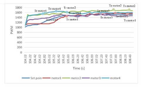
Figure 15. Quadcopter Motor PWM Output With PID
The addition of load to the midpoint of the quadcopter (Figure 15.a) does not affect roll and pitch motion, Thus, affecting the speed and resulting in a steady-state error for all motors. The quadcopter requires 17.47 percent more power on motor 1, 21.19% more power on motor 2, 29.2 percent more on motor 3, and 27.89 percent more power on motor 4 to remain to hover with a 700g load at the midpoint of the quadcopter compared to hovering no burden.
Figure 15.b shows the results of quadcopter testing when given a 200g load on motor 1. The response time on motor 1 is slower because the PID control detects a more significant disturbance in motor 1 pair, namely motor 2, so motor 1 must be slower than motor 2 to balance quickly. The additional load on the two quadcopter motors affects the roll and pitch motion of 25 degrees and 26.5 degrees. The load also affects the speed of the quadcopter, where the motor experiences a steady-state error. The quadcopter requires 3.86 percent more power on motor 1. 9.8 percent more on motor 2., 4.83 percent more on motor 3, and 4.02 percent more on motor 4 to remain able to hover with a 200g load on motor 2 compared to the hover state without load, the most significant error value occurs in motor 2 where the load is stacked, the closer the motor is to the fulcrum, the greater the error.
Furthermore, for testing with 500g Load on Motor 2 and 4, Figure 15.c. Quadcopter takes 1.8 seconds for motor 1, 1.8 seconds for motor 2, 1.2 seconds for motor 3, and 0.8 seconds for motor 4 to reach 90% of the interval to steady-state. The response time on motors 1 and 3 is slower because the PID control detects a more significant disturbance in its partner, motors 2 and 4, to balance itself quickly. The overshoot value is 0.65% on motor 1, 0.93% on motor 2, 0.09% on motor 3, and 1.54% on motor 4, where this percentage value means the power required for each quadcopter motor to reach a steady-state from the overshoot state. Loads that are only focused on their respective partners so that the motor slows down to balance itself. The additional load on the 2 and 4 quadcopter motors affects the roll and pitch motion of 25 degrees and 26.5 degrees. The quadcopter requires 1.79 percent more power on motor 1, 9.8 percent more power on motor
2, 2.4 percent more on motor 3, and 5.03 percent more power on motor 4 to remain to hover with a 500-gram load between the motors 2 and 4 compared to with no-load hovering state.
Overall test results show in Table 2.
Table 2. Test Results for Variation of the Load Support Point
|
Load And No Position |
Tr (s) Ts (s) Tp (s) OS (%) Steady State (s) roll pitch roll pitch roll pitch roll pitch M1 M2 M3 M4 |
|
700 g at the midpoint 2 200 g at M2 500 g at M2 3 and M4 |
1 0.6 2.62 3.82 1.6 1.3 206.6 0.37 20.93 20.93 20.93 20.9 2 2.07 4.5 4.7 3.3 3.5 3.51 53 4.6 11.3 5.3 5.3 1.2 1.1 5.74 6.1 3.3 3.4 0.89 0.35 1.93 8.5 2.2 5.93 |
Based on the research and testing, it can be concluded that PID control can be implemented for the quadcopter balance control system during hovering by determining the PID constants for each roll and pitch motion with the constant of Kp = 0.15, Kd = 0.108, and Ki = 0.05. The quadcopter takes 3 – 6 seconds to return to the 0-degree setpoint when loaded with various loads and positions. The more significant the tilt error in the quadcopter, the longer it takes to return to the 0-degree setpoint.
In further research, it is necessary to add a system that can automatically detect the load's position so that the quadcopter balanced system can reach the balance point more quickly during hovering.
The authors would like to thank the Faculty of Information Technology, Andalas University, for its publication Support.
References
-
[1] M. F. Silva et al., "Design of angular PID controllers for quadcopters built with low cost equipment," in 20th International Conference on System Theory, Control and Computing (ICSTCC), 2016, pp. 216-221.
-
[2] A. Ghosh, H. Roy and S. Dhar, "Arduino Quadcopter," in Fourth International Conference on Research in Computational Intelligence and Communication Networks (ICRCICN), 2018, pp. 280-283.
-
[3] Y. T. Shin and Y. Teh, "Design analysis and considerations of power efficient electronic speed controller for small-scale quadcopter unmanned aerial vehicle," in IEEE 8th Annual Computing and Communication Workshop and Conference (CCWC), 2018, pp. 773-776.
-
[4] Kuantama E, Tarca I, Dzitac S, Dzitac I, Tarca R. "Flight Stability Analysis of a Symmetrically-Structured Quadcopter Based on Thrust Data Logger Information". Symmetry, Vol. 10 No. 7, pp. 291, 2018.
-
[5] A. J. M. Tamayo, C. A. V. Ríos, J. M. I. Zannatha and S. M. O. Soto, "Multirotor modelling and simulation: Screws, S.O.A., Euler angles, quaternions, wind," in 14th International Conference on Electrical Engineering, Computing Science and Automatic Control (CCE), 2017, pp. 1-6.
-
[6] Zabunov, S. and Nedkov, R., "Edge controller – a small UAVs distributed avionics paradigm", Aircraft Engineering and Aerospace Technology, Vol. 92 No. 2, pp. 229-236, 2020.
-
[7] Mendoza-Soto, J.L., Corona-Sánchez, J.J. & Rodríguez- Cortés, H. Quadcopter Path Following Control. A Maneuvering Approach. J Intell Robot Syst 93, 73–84, 2019.
-
[8] Ukaegbu, U.F.; Tartibu, L.K.; Okwu, M.O.; Olayode, I.O. "Development of a Light-Weight Unmanned Aerial Vehicle for Precision Agriculture." Sensors, Vol.21, no.13, p.4417, 2021.
-
[9] G.P. Rible, N.A. Arriola, J.M. Ramos "Modeling and Implementation of Quadcopter Autonomous Flight Based on Alternative Methods to Determine Propeller Parameters", Advances in Science, Technology and Engineering Systems Journal, vol. 5, no. 5, pp. 727741, 2020.
-
[10] W. Xie, D. Cabecinhas, R. Cunha and C. Silvestre, "Cooperative Path Following Control of Multiple Quadcopters With Unknown External Disturbances," in IEEE Transactions on Systems, Man, and Cybernetics: Systems.
-
[11] Rabah M, Rohan A, Han YJ, , Kim SH. "Design of Fuzzy-PID Controller for Quadcopter Trajectory-Tracking". IJFIS, Vol. 18, p. 204-213. 2018.
-
[12] J. M. Ramírez-Rodríguez, Y. E. Tlatelpa-Osorio and H. Rodríguez-Cortés, "Low level controller for quadrotors," in International Conference on Unmanned Aircraft Systems (ICUAS), 2021, pp. 1155-1161.
-
[13] Z. Zhang, "Adaptive Control of Quadrotor UAV Based on Arduino," in 8th International Conference on Power Electronics Systems and Applications (PESA), 2020, pp. 1-4.
-
[14] M. K. Filyashkin, "The Inertance Effect of the Lifting Rotors Rotation Speed Change on the Quality of Automatic Control of a "Heavy" Quadcopter," in IEEE 6th International Conference on Methods and Systems of Navigation and Motion Control (MSNMC), 2020, pp. 129-131.
-
[15] Aisuwarya, R., Marta Yonas, F., & Yendri, D. (). Design of Autonomous Quadcopter Using Orientation Sensor with Variations in Load Fulcrum Point. Lontar Komputer : Jurnal Ilmiah Teknologi Informasi, , Vol. 10, No. 2, p. 84-95, 2019.
174
Discussion and feedback