Performance Improvement of Water Temperature Control using Anti-windup Proportional Integral Derivative
on
LONTAR KOMPUTER VOL. 9, NO. 2, AUGUST 2018
DOI : 10.24843/LKJITI.2018.v09.i02.p03
Accredited B by RISTEKDIKTI Decree No. 51/E/KPT/2017
p-ISSN 2088-1541
e-ISSN 2541-5832
Performance Improvement of Water Temperature Control using Anti-windup Proportional Integral Derivative
Agung Surya Wibowo a1, Erwin Susanto a2
aSchool of Electrical Engineering, Telkom University
Jl Telekomunikasi Terusan Buah Batu Bandung, Indonesia 1agungsw@telkomuniversity.ac.id 2erwinelektro@telkomuniversity.ac.id (corresponding author)
Abstract
In this research, the controller was implemented in water temperature control system. This system has delay and saturation effect that yielded windup effect. It caused instability problem in system which was showed by occurring overshoot and steady state error. Therefore, the implementation of designed controller with anti-windup was needed. This paper described the comparison between 2 methods of controller design, conventional Proportional Integral Derivative (PID) method and PID with Anti-Windup method. The conventional PID method resulted the system that was hardly to achieve the steady state condition. This was caused by the windup effect which made the system saturated so that the integrator part in the PID would get bigger accumulatively. The solution to fix this instability problem was by using the PID with anti-windup. The experimental result showed that the output response from the control system with the anti-windup PID was able to omit overshoot around 18.75 % and steady state around 5%.
Keywords: Water temperature control, Anti-windup, PID, Saturation, Integrator, Steady state error, Overshoot
Design of Proportional Integral Derivative (PID) control in various fields such as in industrial areas, experimental laboratories and household applications has been encountered [1-7]. In particular, researches about water temperature control system with PID have been reported [8], [9]. Figure 1 shows the built water’s temperature control system module and Personal Computer (PC) as a data logger. Data logger had an ability to collect data that needed for further benefit such as controlling and management processing [10].
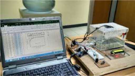
Figure 1. Water’s temperature control system
This research is very interesting because the control system has a slowly response and has time delay in its open loop system. If we deal with a slowly system, it is possible that the output of the actuator will be saturated. Saturation will make the performance of control system is worse. For example, the problem appeared when the control system used PI or PID controller. The integrator value of PI or PID controller will accumulate. In fact, the actuator has been saturated and the total of sum in integrator part will not affect the actuator output. This effect is called as effect of windup.
The problem arises when the output is over the set point value. The integrator which keep counting continuously makes the system’s output is hard to reach back to the set point. To handle this problem, we should make limitation at integrator value so that, the integrator value will stop counting. The method for limiting this integrator value is called anti-windup system [9], [11]. If it is embedded to PID controller then the system is totally called the PID with anti-windup. Figure 2 shows the anti-windup PID block diagram which was realized for simulation and experimental results.
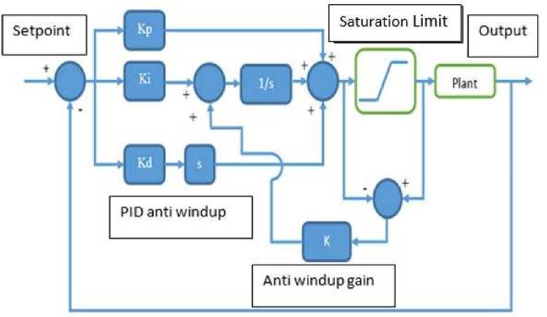
Figure 2. Block diagram of closed loop control system with anti-windup PID
This research aims to realize the anti-windup method for water temperature control which has delay and slow response. Even though several studies on anti-windup PID have been reported; for examples see [9], [12], to our knowledge, there has been no implementation on the water heater control using anti-windup PID. In [9], delay phenomenon was not considered to the implemented system; water level system; so that the windup effect was less than of this research. In [12], authors used Proportional Integral (PI) Anti-windup for faster system to ours, i.e. Brushless Direct Circuit (DC) Motor. The faster response the less windup effect occurred because the system was able to reach set point easily. This research also shows the advantages of using anti windup in reducing overshoot, ripple phenomenon and steady state error.
This research was realized into two steps. The first was designed with a conventional PID and the second one was designed with ant-windup PID. From both steps, we compared and analyzed which one that has better response. Saturation’s effect caused a windup problem in system with conventional PID whereas in the system with anti-windup PID, the problem can be reduced effectively
Many applications of PID controller used in any industry fields. Several industries such as process control system or manufacture that use robotic system involve the PID controller. The PID controller is often implemented in digital computer practically. The present of digital computer makes the PID controller become easier to be modified and improved different from if it is implemented in pure analog computation using analog electronic hardware. There are some modifications in PID controllers, for example flexible PID [2], [6], decentralized PID [3], and PID with gain scheduling [9].
The PID algorithm consists of 3 components. There are proportional, integral, and differential gains. All of components will be proceed parallelly and simultaneously. Equation 1 shows the transfer function of generalized PID.
PID (s)=Kp+^ + Kd.s (1)
Each of components of PID controller has a specific usage. The proportional gain is used to improve the time response but sometimes, bigger proportional gain makes the system relatively more unstable that is indicated with the bigger overshoot and more ripples. Integral gain is used to reduce or eliminate the error steady state. Integral gain should be set correctly, otherwise, the response of system will be slowly to reach the setpoint. Too big integral gain also makes the system response has more oscillations. It can be seen in Figure 3.
The final part, differential gain can smooth the system response, so that the response tends to have a small ripple and no oscillation, because this part reduces the differential error. Differential gain can also stabilize when the system is unstable.
These following figures below are the simulation results from any PID constants setting.
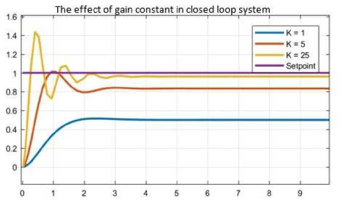
Figure 3. Simulation results that show the effect of gain constant in closed loop system
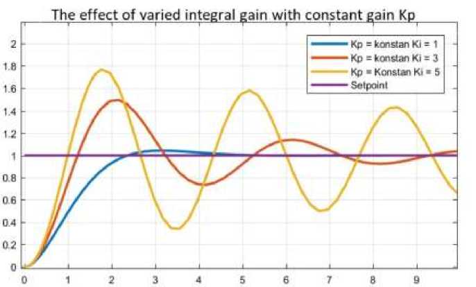
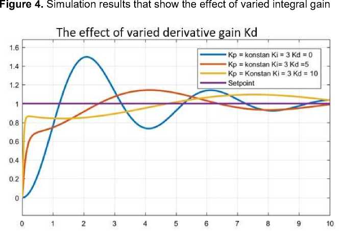
Figure 5. Simulation results that show the effect of varied derivative gain
In water temperature control system, saturation effect can appear in its actuator that exceed Pulse Width Modulation (PWM) signal. In microcontroller, generated PWM signal has saturation value in 0 and 255. Figure 6 and 7 show the system simulation when saturation effect is not given.

Figure 6. Block diagram of PID control for system without saturation
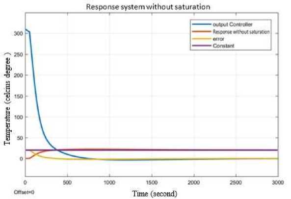
Figure 7. Response of PID control for system without saturation
Although theoretically PID controller is applied for the linear system, in applied design it is needed to add a non-linearity effect. One of the non- linearity effect is saturation effect that may possibly occur in actuator or plant of the system. It can be seen in Figure 7. that the system response still can reach the setpoint. The problem has not appeared yet, when the closed loop system does not include the saturation effect. But, on the other side, if the saturation effect is added to the simulation, see Figure 8, then the response was shown in Figure 9 below.

Figure 8. Block diagram of PID control for system with saturation
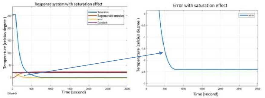
Figure 9. Response of PID control for system with saturation
The steady state error appears, if the saturation effect is added. Different from the first simulation, steady state error can be zero when the saturation effect is not given.
The counting process at integral part in PID does not change the output of actuator because of the saturation effect. Phenomena that make the integral part is getting bigger is defined as windup effect. To handle this problem, the system must add an anti- windup system. One of anti-windup system method is back calculation integral model method shown in Figure 2. Basically, anti-windup system will hold the integral value is not getting bigger when the output of actuator is saturated. Integral value can be decreased when the actuator output over the saturation limit. So, the anti-windup system will work only if saturation state is happened. Saturation limit in this system has range from 0 – 255 adjust to PWM signal. How big the decreasing value to hold the integral value depends on how big the gain factor of anti-windup that added to anti-windup system.
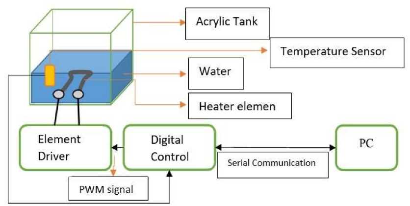
Figure 10. Block diagram of water temperature control system hardware
The actuator of this control system was heater element controlled by optocoupler and Triac circuit. The optocoupler and Triac circuit will act as switch that make the AC voltage given to the heater is on and off. PWM signal counted from PID controller will be the input to the optocoupler and Triac circuit. Figure 11 shows the optocoupler and Triac circuit as a driver for heater element.
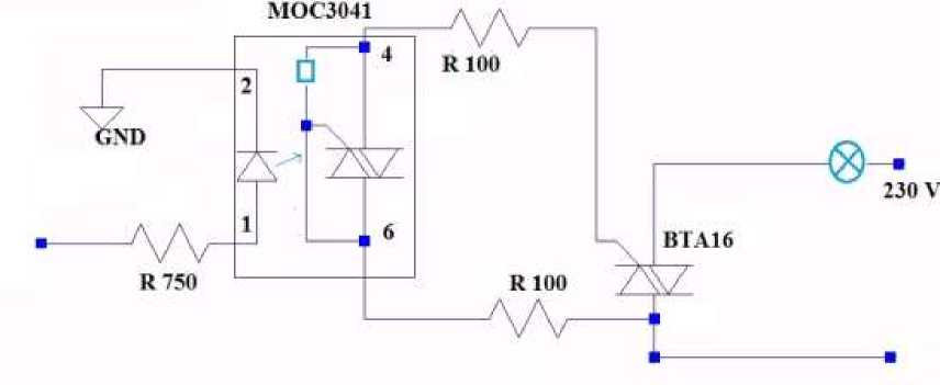
Figure 11. Heater element driver circuit (optocoupler and Triac circuit).
The DS18B20 temperature sensor was used as feedback signal. This sensor will sense the temperature of water in tank and send the result to Arduino via I2C serial protocol. Figure 12 shows the temperature sensor DS18B20.
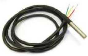
Figure 12. Temperature Sensor DS18B20
Finally, Arduino Uno platform was used as a digital controller. In this platform, anti-windup PID system was implemented digitally by program code. Figure 13 shows the source code of antiwindup PID. The code was divided into two parts. The first part was conventional PID that will compute the error of temperature. Another part was anti-windup system which was always checking when the saturation happened.
vcid. pid ()
{ p = kp*error,∙∣ i=i+(ki*error); d = M*(error-error_sebelum); if (initd=l) {initd=0; d = 0;}
error sebelum =error;
outpid = p+i+d;
if (outpid >255){
i= i-(ka*(outpid-255));// antiwindup outpid = 255;
}
if (outpid < 0 ){
i= i-(ka*outpid); ZZantiwindup
outpid =0;
}
pwm = outpid;
}
Figure 13. PID anti-windup code program
If the code is analyzed, the anti-windup system will work when the output of PID is bigger than 255 or smaller than 0. Ka is the gain factor that make how big the decreasing of integral value can happen. If Ka is set to zero, then the anti-windup system part in program code will not work and the anti-windup PID will be same as the conventional PID (without anti-windup).
System modeling was done by measuring how long the time delay and see whether the open loop system has likely stable or not. If the system was likely stable, then the system can be approximated by first order system complemented with delay. Otherwise, if the system was likely unstable then it can be approximated by adding an integrator to first order system with delay.
After some observation to system, it can be found that the system has time delay about L (time delay) = 50 seconds. Looking in real condition if water in room condition temperature 250 C, it will increase to 750 C when the water was heated by heater in PWM equals to 255. Time response to raise the water temperature from 250 C to 750 C degree was about 500 seconds. From here, gain K can be found by equation 2.
f 75-25 1
K _ tsoo—5θJ ≅ 2/4500 (2)
From equation 2 the open loop system can be found like equation 3 with the constant ‘a =1’ was chosen arbitrarily
F(s)= τ( s-)=K.
v j PWM(s) .(s+a)

(3)
The control system of water temperature was done in 3 steps. First step was to check whether the open loop system is suitable with the real condition or not.
The testing was done by giving step input with amplitude 255 to the transfer function at equation 3.

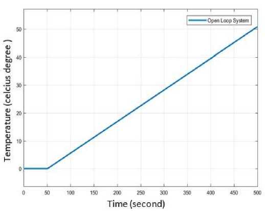
Figure 14. Block diagram and its open loop response
The block diagram of simulation is shown in figure 14. It can be seen in Figure 14 that the transfer function in equation 3 satisfies the desired real condition. In graph at Figure 14 shows the output graph of open loop system. Temperature of water was raised 500 C from zero in 500 seconds.
The next step is closed loop system simulation using PID conventional with the value of parameter of PID are show at Table 1.
Table 1. Parameter value of the conventional PID controller
SP Kp Ki Kd Ka
600C 12.2 0.016 0 0
The simulation result for the closed loop control system with the conventional PID can be seen from its output in Figure 15. It was shown that the output has a steady state error about -200 C.
The setpoint was set to 600 C and the output is 800 C.
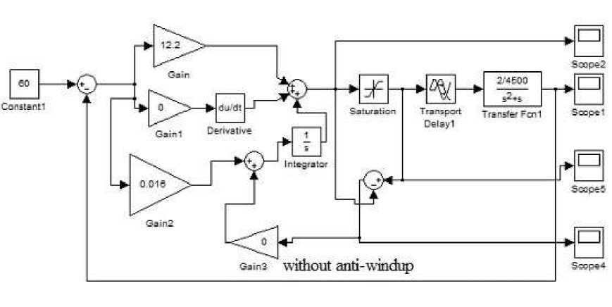
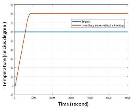
Figure 15. Block diagram and response of closed loop control system with conventional PID, without anti-windup
The final step is the simulation of closed loop control system with PID anti-windup controller. In this simulation the gain of anti-windup Ka is added to the controller. All parameter used in the controller are shown in Table 2.
Table 2. Parameter value of Anti-Windup PID controller
|
SP |
Kp |
Ki |
Kd |
Ka |
|
600 C |
12.2 |
0.016 |
0 |
1 |
The simulation result can be seen in Figure 16. It can be found that the last simulation is better than the first simulation. The first simulation referred to system with conventional PID showed steady state error 33.33% whereas there was no steady state error occurred in output for the simulation of PID with anti-windup in the last simulation.
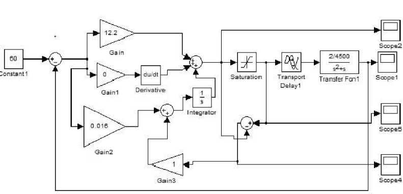

Figure 16. Block diagram and result of closed loop system with anti-windup PID controller
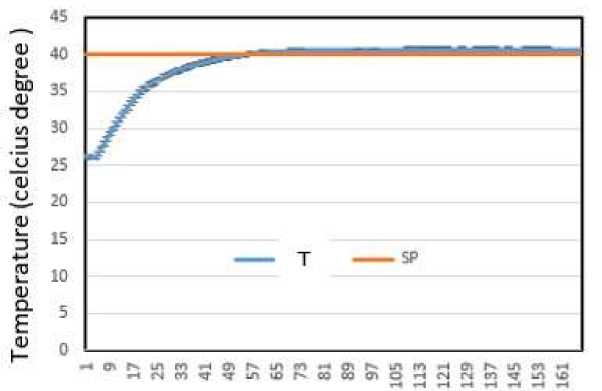
The implementation of water temperature control system was done by taking 1 liter of water in tank. The set point was set to 400 C and the initial condition of water temperature was same as the room temperature 260 C.
The experiment for implementation was done in 2 parts. The first experiment was for the closed loop system with conventional PID and the second experiment was for the closed loop system with PID anti-windup. The response of closed system was observed by PLX – DAQ software. This software was made by parallax. It was usually used to log data output of water temperature that automatically connected and sent to MS Excel. It was also automatically plotted the response into a graph. Figure 13 shows the PLX – DAQ software.
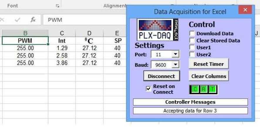
Figure 17. PLX-DAQ software application
The parameter that was used in experiment of closed loop system without anti-windup can be seen in Table 3.
Table 3. Conventional PID parameter values
SP Kp Ki Kd Ka Ts (Time Sampling)
400 C 30 0.1 40 0 20
In Figure 18, it can be shown that overshoot was very big, around 18.75%. The response was also hard to closed to the set point and had steady state error 5%. Therefore, it can be concluded that this response was not good.
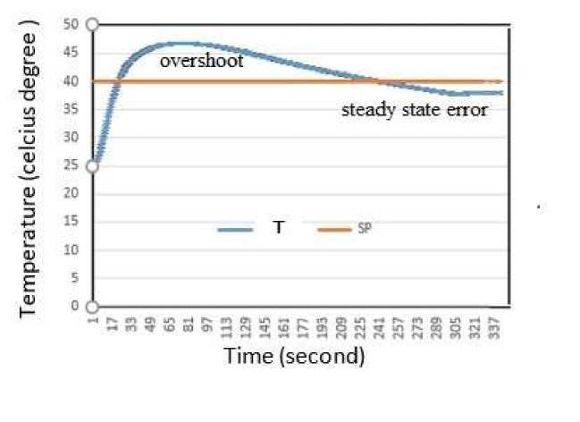
Figure 18.
Response of closed loop system with conventional PID controller
The parameter that was used in experiment of closed loop system with anti-windup can be seen in Table 4.
Table 4. Anti-windup PID parameter values
|
SP |
Kp |
Ki |
Kd |
Ka |
Ts (Time Sampling |
|
400 C |
30 |
0.1 |
40 |
1 |
20 |
Time (second)
Figure 19. Response of closed loop system with anti-windup PID controller
From the result of implementation of anti-windup PID, the response of the system was better than the system using conventional PID. The response system with anti-windup had steady state error closed to zero and it also had no overshoot.
The implementation of anti-windup PID was worked very well in water temperature closed loop control system. It was better than conventional PID did. The experiment showed that the overshoot and steady state error of the closed loop system with conventional PID was bigger than that of closed loop system with anti-windup PID.
For the next research, it is needed to design the water temperature control system by finding the accurate model. So, the parameter of PID controller can be synthesized analytically. One of method using model based is smith predictor controller. It is also usually used for designing system with delay effect such as water temperature control system.
This research was supported by internal research grant of Telkom University. It is cooperated with assistant’s Control System Laboratory. In the future, this research will be conducted for simple application learning and to demonstrate the closed loop control system especially in water temperature control. Hopefully, the students will become more understand about the concept and basic knowledge of control system by trying to implement varied controllers to this experimental device.
References
-
[1] H. Jeon, J. Lee, S. Han, J.H. Kim, C.J Hyeon, H.M. Kim, H. Kang, T.K Ko, and Y.S.S. Yoon, “PID Control of an Electromagnet-Based Rotary HTS Flux Pump for Maintaining Constant Field in HTS Synchronous Motors”, IEEE Transactions on Applied Superconductivity, vol. 28, no. 4, 5 pages, 2018
-
[2] K. Lapa and K. Cpałka, “Flexible Fuzzy PID Controller (FFPIDC) and a Nature-Inspired Method for Its Construction”, IEEE Transactions on Industrial Informatics, vol. 14, no. 3, pp. 1078-1088, 2018.
-
[3] Q Chen, Y. Tan, J. Li and I. Mareels, “Decentralized PID Control Design for Magnetic Levitation Systems Using Extremum Seeking”, IEEE Journals & Magazines, vol. 6, pp. 3059 – 3067, 2018.
-
[4] H. Wang and Yonglin, “Dynamic Modeling of PID Temperature Controller in a Tunable Laser Module and Wavelength Transients of the Controlled Laser”, IEEE Journal of Quantum Electronics, vol. 48, no.11, pp. 1424-1431, 2012.
-
[5] V. de Oliveira and A. Karimi, “Robust and Gain-Scheduled PID Controller Design for Condensing Boilers by Linear Programming”, IFAC Proceedings Volumes, vol. 45, no. 3, pp. 335-340, 2012.
-
[6] F-C. Liu, L-H. Liang, J-J. Gao, “Fuzzy PID Control of Space Manipulator for Both Ground Alignment and Space Applications”, International Journal of Automation and Computing, vol 11, no. 4, pp. 353-360, 2014.
-
[7] A.K. Theopaga, A. Rizal, E. Susanto, “Design and Implementation of PID Control based Baby Incubator”, Journal of Theoretical and Applied Information Technology, vol. 70, no 1, pp.19-24, 2014.
-
[8] T. Hondianto, E. Susanto, A.S. Wibowo, “Model Driven PID controller in water heater
system”, International Journal of Electrical and Computer Engineering vol. 6, no 4,
pp.1673-1680, 2016.
-
[9] S.C. Pratama, E. Susanto, A.S. Wibowo, "Design and Implementation of Water Level
Control using gain scheduling PID back calculation integrator anti-windup," The 2016
International Conference on Control, Electronics, Renewable Energy and Communication (ICCEREC), Bandung, 2016, pp. 101-104.
-
[10] I. N. Piarsa, P.B.S Togantara, “Sistem Monitoring Spesifikasi dan Utilitas Host di Jaringan Komputer Berbasis Web”, Lontar Komputer, Vol 3, No. 2, 2012, hal. 179-187.
-
[11] A. Pati and R. Negi, “An Anti-windup Control Strategy to Actuator Saturating Input Voltage for Active Magnetic Bearing System”, The International Journal for Computation and Mathematics in Electrical and Electronic Engineering, vol. 35 no. 3, pp.1046-1063, 2016.
-
[12] A. Shyam and Febin Daya J L, "A comparative Study on The Speed Response of BLDC Motor using Conventional PI Controller, Anti-windup PI Controller and Fuzzy Controller," 2013 International Conference on Control Communication and Computing (ICCC), Thiruvananthapuram, 2013, pp. 68-73.
94
Discussion and feedback