Coral Stone Installation On the Substation Grounding System In Limestone
on
Journal of Electrical, Electronics and Informatics, Vol. 6 No. 1
17
Coral Stone Installation On the Substation Grounding System In Limestone
I Gusti Ngurah Janardana1, I Wayan Arta Wijaya2
-
1,2 Departement of Electrical Engineering, Faculty of Engineering Udayana University, Bukit Jimbaran
Bali, Indonesia janardana@unud.ac.id
Abstract- The step voltage and touch voltage exceed the maximum limit due to overcurrent to the ground flowing in the equipment grounding area which is dangerous for the equipment and people in the vicinity. The ground at the switchyard location is filled with coral above the ground level. The purpose of this study was to determine the thickness of coral in the grounding system of switchyard equipment in calcareous soil. The analytical method of this research is to calculate the results of the thickness of the coral to get the standard value of IEEE-80-2013. The result of this research is that the installation of 0.15 meters of coral when wet or dry produces the best step voltage and touch voltage values when compared to the thickness of 8 cm (0.08 meters) of coral stone to 14 cm (0.14 meters).
Idex Term : Grounding, Coral, Limestone Soil
-
I. Introduction1
The voltage at the ground surface which can result in the occurrence of touch voltage and step voltage exceeds the allowable human safety limit due to a ground fault current flowing in the equipment grounding area. Earthing or often called grounding at the switchyard location is filled with a layer of coral above the ground surface. The thickness of the coral layer is between 8 cm (0.08 meters) to 15 cm (0.15 meters) with a disturbance time of 1 second depending on the type of soil where the equipment is located according to IEEE Std 80-2013[1].
Some preliminary measurements have been carried out, on limestone soil the soil value = 263.76 ohm-meters has been obtained. Measurement of soil resistivity on sandy soil types obtained soil = 37.60 ohm-meters and measurements on clay soil types obtained soil = 80.38 ohm-meters. Based on the results of preliminary measurements, it is known that each type of soil has different soils and causes the step stress and touch stress that occurs will be different, so that it has an impact on the difference in the thickness of coral required at the location of each type of soil [2].
So it is important to do research on the thickness of coral on calcareous soil in the earthing system of electrical equipment substations.
-
II. LITERATURE REVIEW
-
2.1 The Relationship of Grounding Resistance to the Human Body
-
When a person touches the affected equipment, there will be a current flowing in the person's body. Through the hands, electric current will flow to the feet and continue to the ground and harm the human body[3] [4].
-
2.2 Human Body Resistance
The resistance of the human body to the magnitude of the electric current ranges from 500 to 100,000 Ohms depending on the voltage, the state of the skin and the electric current flowing in the human body. Based on research by experts, as an approach, the value of the human body's resistance is 1000 Ohms [4] [5] [6] [7].
-
2.3 Current Through The Human Body
It is very difficult to determine the ability of the human body to the amount of electric current to a limit that is not dangerous. Nerve stimulation will be felt and there is a vibration that is not dangerous when with alternating current and direct current, but will only feel a little hot. A person will result in fainting and even death if the current that passes through his body is greater than the current that
affects the muscles. because the electric current affects the heart until its work stops and blood circulation does not work [4].
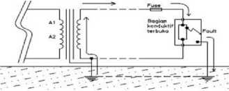
Figure 1. Path for Fault Current
-
2.4 Allowable Touch Voltage
Table I provides the criteria for the duration of the disturbance and the allowable touch voltage
TABLE I
PERMISSION DURATION AND TOUCH VOLTAGE[8].
|
No |
Disturbance duration t (seconds) |
Touch Voltage (Volt) |
|
1 |
0,1 |
1980 |
|
2 |
0,2 |
1400 |
|
3 |
0,3 |
1140 |
|
4 |
0,4 |
990 |
|
5 |
0,5 |
890 |
|
6 |
1,0 |
626 |
|
7 |
2,0 |
443 |
|
8 |
3,0 |
362 |
-
2.5 Allowable Step Voltage
Table II provides the criteria for the duration of the disturbance and the allowable touch voltage.
TABLE II
PERMISSION DURATION AND VOLTAGE STEP
ALLOWED[8
|
No |
Disturbance duration t (seconds) |
Step Voltage (Volt) |
|
1 |
0,1 |
7000 |
|
2 |
0,2 |
4950 |
|
3 |
0,3 |
4040 |
|
4 |
0,4 |
3500 |
|
5 |
0,5 |
3140 |
|
6 |
1,0 |
2216 |
|
7 |
2,0 |
1560 |
|
8 |
3,0 |
1280 |
-
2.6 Calculation of Maximum Step Voltage
Maximum step voltage equation [8].
^iTK n -r xn of g......q..........................(1)
0,75Xc+0,S5⅛
For the calculation of finding the value of the correction factor (Ks) equation is used[8].
^2 w "^D + h^n ^ Q'5 ........(2)
........
With information:
⅛ = Actual step voltage (Volt)
Ks = Correction factor of step voltage
K; = 0,656 + 0,172 n
K; = As a correction factor when the extremity current increases in Grid
p = A Resistant location soil type (Ω-meters)
^G = The amount of current flowing in the Grid (Amperes)
^C = Total length of conductor
~j∏ = Total length Rod . electrode
D = Distance between parallel conductors on the Grid
d = diameter Grid conductor
h = Depth of electrode installation from ground level
n = Total number of parallel conductors in the Grid
(Largest number)
-
2.7 Soil Classification
Soil can be classified based on a technical point of view as follows[10]:
-
1. Clay
-
2. Silt
-
3. Sand
-
4. Pebbles (gravel)
-
2.8 Use of Coral
The purpose of laying gravel in the switchyard area is to[11]:
-
1. So that the fault current flows directly into the ground and not along the ground surface area when there is a fault current to the ground.
-
2. When the transformer is disturbed (transformer oil leaks) the pool of transformer oil can be prevented, if the oil burns, the spread of fire can be avoided and does not disturb other equipment in the area.
-
3. As a medium that provides a high resistance layer between the personnel who step on it and the soil under the gravel, because the gravel acts as an insulator.
-
4. Does not interfere with the movement of people and the mobility of equipment in the switch yard.
-
5. The size of the steps of people walking in the area can be reduced,
-
6. Inhibit the growth of bushes and grass in the switchyard
-
III. RESEARCH METHODS
-
3.1 Location and Time of Research
-
The research was carried out at 5 (five) location points with limestone soil types between Jimbaran and Uluwatu, for the rainy season in November 2020 and the dry season in June 2021.
-
3.2 Research Implementation Design
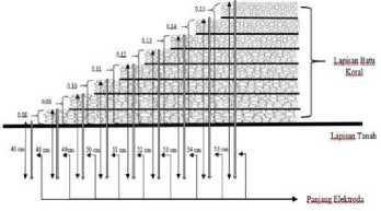
Figure 2. Coral Rock Thickness and Electrode Length
-
3.3 Research Flowchart
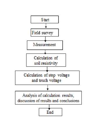
Figure 3. Research Flowchart
The following is an explanation in Figure 3:
Step 1. Start
Preparation by preparing research materials.
Step 2. Field survey,
Determine the research location to find limestone soil data.
Step 3. Measurement
Measuring soil resistance in limestone soils, and measuring coral rock resistance with each coral thickness of 0.08 m - 0.15 m during the rainy and dry seasons.
Step 4. Calculation of soil resistivity
Calculation of soil Rho (resistance of soil type) Limestone and the addition of coral with a variation of each coral thickness 0.08 m – 0.15 m based on the measurement data to be able to calculate the allowable step stress and touch stress.
Step 5. Calculation of step voltage and touch voltage
Calculating the allowable touch stress and step stress based on the thickness of the coral so that the thickness of the coral that is best installed for earthing the substation on limestone soil will be calculated.
Step 6. Analysis of calculation results, discussion of results and conclusions
After getting the calculation results, it can be discussed and a conclusion can be drawn
-
IV. RESULTS AND DISCUSSION
-
4.1 Research Measurement Results
-
The results of soil Rho measurements (soil resistance) carried out at several locations along the Jimbaran to Uluwatu route on limestone soil during dry conditions of the dry season were 276.32 Ohm-m. While the results of the measurement of the highest soil type resistance value in wet conditions (rainy season) from the 5 measurement locations are 187.144 Ohm-m. The result of soil resistivity measurement with the addition of coral with a thickness variation of 0.08 meters to 0.15 meters on dry limestone soil
is 13.816 Ohm-m. The result of soil resistivity measurement with the addition of coral with a thickness variation of 0.08 meters to 0.15 meters in wet limestone soil is 8,792 Ohm-m.
-
4.1 Calculation Results and Discussion
-
4.1.1 Calculation of allowable touch voltage
-
Calculation of the allowable step stress based on the thickness of the layer of coral on calcareous soil. Before calculating the touch stress and step stress, it is necessary to find the reduction factor based on the coral layer from 8 cm (0.08 meters) to 15 cm (0.15 meters) using the equation:
D wΓl--J
ls°p≡ 1 2ħr+0,W
SO,M - 1 2x0.08+0,09
Csθ,oβ = 4.8084
With the same equation, the value of the reduction factor is obtained with a thickness of coral from 8 cm (0.08 meters) to 15 cm (0.15 meters). Soil Rho (resistance of soil type) on dry calcareous soil is 276.32 -meters. The results of the calculation of the touch stress based on the thickness of the
coral on a dry calcareous soil using the equation:
Et 70 = [1000 + 1,5∕⅛ Cs] 5^
Description :
“i 7D = permissible touch stress for a person weighing 70 kg ( V)
Ps = Coral resistivity (Ω-m)
P = resistivity of the soil under the coral layer (Ω-m)
^S = reduction factor
⅛ = coral layer thickness (m)
t = length of interruption time(s)
As in the above equation, the results of the calculation of the touch stress are obtained based on the thickness of the
coral on a dry calcareous soil:
Et 70 = [1000 + 1,5.¾ Cs] ^
Et 70 = [1000 + 1,5 x 23,864 x 4,8084] ^
Et7D = 172,3020Volt
According to the same formula, the value of the touch stress
is obtained with a thickness of coral from 8 cm (0.08 meters) to 15 cm (0.15 meters) on dry calcareous soil as shown in the table below.
TABLE III.
RESULT OF CALCULATION OF TOUCH VOLTAGE ON DRY SOIL AND STONE CONDITION WITH CORAL THICKNESS 0.08 METERS TO 0.15 METERS
|
No |
Coral Rock Thickness (m) |
Reduction Factor |
Touch Voltage (V) |
|
1 |
0,08 |
4,8084 |
172,3020 |
|
2 |
0,09 |
4,7407 |
170,6329 |
|
3 |
0,1 |
4,7059 |
169,1558 |
|
4 |
0,11 |
4,7016 |
167,8336 |
|
5 |
0,12 |
4,7273 |
166,6381 |
|
6 |
0,13 |
5,0945 |
165,3419 |
|
7 |
0,14 |
5,2162 |
164,3354 |
|
8 |
0,15 |
5,3846 |
163,4038 |
The soil type resistance on calcareous soil in a wet state is 187.144 -meters. The following is a calculation of the touch stress based on the thickness of the coral on a calcareous soil in a wet state using the equation:
Et70 = [1000 + 1,5⅛ Cs] 2^
Like the equation above, the results of the calculation of the touch stress are obtained based on the thickness of the coral on calcareous soil in a wet state:
Et70 = [1000 + l,5ps Cs] 5^
Et 70 = [1000 + 1,5 x 20,096 x 3,9925] 2^-
Ef 70 = 172,3020Volt
With the same formula, the value of the touch stress with the thickness of coral from research on calcareous soils in a wet state is obtained as shown in the table below
TABLE IV
RESULTS OF CALCULATION OF TOUCH VOLTAGE ON WET CONDITIONS OF SOIL AND CORAL STONES WITH CORAL STONE THICKNESS 0.08 METERS TO 0.15 METERS
|
No |
Coral Rock Thickness (m) |
Reduction Factor |
Touch Voltage (V) |
|
1 |
0,08 |
3,9925 |
164,6914 |
|
2 |
0,09 |
3,9778 |
163,5246 |
|
3 |
0,1 |
3,9926 |
162,4804 |
|
4 |
0,11 |
4,3145 |
161,3388 |
|
5 |
0,12 |
4,4215 |
160,4697 |
|
6 |
0,13 |
4,5743 |
159,6684 |
|
7 |
0,14 |
5,0175 |
158,8203 |
|
8 |
0,15 |
4,8175 |
157,7230 |
The calculation results show that as the thickness of the coral stone increases, the touch stress decreases and with the same thickness the value of the touch stress in the dry state is greater than the value of the touch stress in the wet state. Based on the standard allowable touch voltage as in table 1 with a disturbance duration of 0.1 seconds is 1980 volts, the thickness of 0.15 meters of coral stone has the best value, both in wet and dry conditions on limestone soil.
-
4.2.2 Allowable step voltage
Before calculating the touch stress and step stress, it is necessary to find a reduction factor based on the thickness of the coral from the study using the equation:
0.09Γ1--⅛
ls°p≡ ^ 1 2⅛l+009
S0,M - 1 2x0.08 + 0,09
cs 0,08 = 4.8084
With the same formula, the value of the reduction factor with the thickness of coral is obtained from the study. The
soil type resistance on dry calcareous soil is 276.32 -meters. Calculation of step voltage using the equation:
Es70 =[1000 +6ftCs]^
With the above equation, the results of the step stress calculation are obtained based on the thickness of the calcareous soil coral in a dry state:
Es70 =[1000 +6ftCs]^
Es70 = [1000 + 6 x 276,32 x 4,8084] ≡
Es70 = 265,0928 Volt
With the same formula, the step stress values with the thickness of the coral are obtained from research on dry limestone soils as shown in the table below.
TABLE V
RESULTS OF CALCULATION OF STEP VOLTAGE ON DRY SOIL AND CORAL CONDITIONS WITH CORAL THICKNESS 0.08 - 0.15 METERS
|
No |
Coral Rock Thickness (m) |
Reduction Factor |
Step Voltage (V) |
|
1 |
0,08 |
4,8084 |
265,0928 |
|
2 |
0,09 |
4,7407 |
257,9623 |
|
3 |
0,1 |
4,7059 |
251,6522 |
|
4 |
0,11 |
4,7016 |
246,0036 |
|
5 |
0,12 |
4,7273 |
240,8962 |
|
6 |
0,13 |
5,0945 |
235,3585 |
|
7 |
0,14 |
5,2162 |
231,0589 |
|
8 |
0,15 |
5,3846 |
227,0790 |
The soil type resistance on calcareous soil in a wet state is 187.144 -meters. Calculation of step stress based on the thickness of coral on calcareous soil in a wet state uses the following equation:
Es70 = [1000 + 6ft Cs] 2^
With the above equation, the results of the step stress calculation based on the thickness of coral on calcareous soil in a wet state are obtained as follows:
Es70 = [1000 + 6ps Cs] 2≡
r , 0,157
Es70 = [1000 + 6 x 187,144 x 3,9925] —=-
" Vl
Es70 = 232,5797 Volt
With the same formula, the step stress value with the thickness of coral is obtained from research on wet calcareous soil as shown in the table below.
TABLE VI
RESULTS OF CALCULATION OF STEP STRESS CONDITIONS OF CORAL STEP WITH WET
CONDITION WITH THICKNESS 0.08 - 0.15 METERS
|
No |
Coral Rock Thickness (m) |
Reduction Factor |
Step Voltage (V) |
|
1 |
0,08 |
3,9925 |
232,5797 |
|
2 |
0,09 |
3,9778 |
227,5947 |
|
3 |
0,1 |
3,9926 |
223,1341 |
|
4 |
0,11 |
4,3145 |
218,2567 |
|
5 |
0,12 |
4,4215 |
214,5442 |
|
6 |
0,13 |
4,5743 |
211,1208 |
|
7 |
0,14 |
5,0175 |
207,4975 |
|
8 |
0,15 |
5,6813 |
204,0530 |
The calculation results show that as the thickness of the coral stone increases, the step stress decreases and with the same thickness the step stress in the dry state is greater than the step stress in the wet state. Based on the standard voltage in table 2 with a disturbance of 0.1 seconds, it is 7000 volts. Even though with a thickness of 8 cm (0.08 meters) to 15 cm (0.15 meters) coral still has a safe (good) step stress value, but 0.15 meter coral thickness has the best value, both in wet and dry conditions. dry on limestone soil.
-
V. CONCLUSION
The conclusion from the results of this study is that the thickness of coral from 0.08 meters to 0.15 meters has a safe (good) touch voltage value according to the IEEE Std 80-2013 standard with a disturbance duration of 0.1 seconds below 1980 volts. However, the thickness of 0.15 meters of coral stone has the smallest (best) value in wet or dry conditions. As for the step voltage on limestone soils, the thickness of the coral based on research has a safe (good) step voltage value according to the IEEE Std 80-2013 standard with a disturbance duration of 0.1 seconds is below 7000 volts. However, the thickness of coral 15 cm (0.15 meters) has the smallest (best) value in wet or dry conditions on limestone soils.
-
6. REFERENCES
-
[1] J. Agung. Perancangan Sistem Pengetanahan Peralatan di Gardu Induk PLTU IPP (Independent Power Producer) Kaltim 3. Malang : Universitas Brawijaya. 2015.
-
[2] IPN. Suciawan.,IGN. Janardana., IWA. Wijaya, IWA. Pengaruh Ketebalan Batu Koral Pada Tanah Lempung Dan Tanah Berpasir Terhadap Tegangan Langkah Dan tegangan Sentuh. Jurnal SPEKTRUM; Volume 8 No. 1 Maret 2021.
-
[3] A. Arismunandar. Buku Pegangan Teknik Tenaga Listrik Gardu Induk. Jakarta: Pradnya Paramita. 1991.
-
[4] TS. Hutauruk. Pengetanahan Netral Sistem Tenaga dan Pengetanahan Peralatan. Jakarta : Erlangga. 1999.
-
[5] KRA. Setyawan., IGN. Janardana., NP. Satriya Utama. Analisis Sistem Pembumian untuk Mengamankan Instalasi Listrik di Program Studi Teknik Elektro Fakultas Teknik Universitas Udayana Jimbaran Bali Majalah Ilmiah Teknologi Elektro Volume 17, No. 2 Mei – Agustus 2018. Jimbaran : Program Studi Teknik Elektro Universitas Udayana. 2018.
-
[6] KM. Mahadewi., IGN. Janardana., IWA. Wijaya. Analisis Tegangan Langkah dan tegangan Sentuh Serta
Perencanaan Sistem Pembumian Pada Pembangunan Substation VVIP. Di Bandara Internasional I Gusti Ngurah Rai Bali. Journal SPEKTRUM Volume 6, No. 1 Maret 2019. Jimbaran : Program Studi Teknik Elektro Universitas Udayana. 2019.
-
[7] A. Latif. Probabilitas Tegangan Sentuh dan Tegangan Langkah di Lokasi Rencana Gardu Induk 500 kV Antosari. Bali: Universitas Udayana. 2016.
-
[8] IEEE Standard 80 - 2000. (2013). Guide For Safety In Ac Substation Grounding. New York
Pembangunan Substation VVIP. Di Bandara Internasional I Gusti Ngurah Rai Bali. Journal SPEKTRUM Volume 6, No. 1 Maret 2019. Jimbaran : Program Studi Teknik Elektro Universitas Udayana.
-
[9] IM. Suartika. Sistem Pembumian (Grounding) Dua Batang Sistem Pengaman Tenaga Listrik. Bali: Universitas Udayana Bali. 2017
-
[10] S. Hadjowigeno. Klasifikasi Tanah dan Pedogenesis. Jakarta : Pressido. 1993.
-
[11] R. Andira. Analisis Sistem Pertanahan Grid pada Gardu Induk 2 x 500 MVA Galang. Medan: Universitas Sumatra Utara. 2018.
Discussion and feedback