Operation of LED Light as Emergency Lighting Resource DC with Charger Control Based Arduino Uno ATmega
on
Journal of Electrical, Electronics and Informatics, Vol. 1 No. 2, September 2017
13
Operation of LED Light as Emergency Lighting Resource DC with Charger Control Based Arduino Uno ATmega
I Wayan Rinas1*, I Made Suartika2, Anak Agung Maharta Pemayun3, and I G. A. P. Raka Agung4
-
1,2,3,4 Departement of Electrical Engeneering
Faculty of Engeneering Udayana University Bali - Indonesia *rinas@unud.ac.id
Abstract - Lighting is very important to support the activities of human life. To maintain the continuity of lighting can use power source from genset or battery. Now many manufactured LED (light emitting diode) bulb type which is energy saving with life time up to 50.000 hours. LEDs of this type can be operated with AC and DC current. The design control charger based Arduino Uno ATmega micro controller is used as a control system for charging and turning on LED lights. In this research the measurement of light intensity is done at 220 volt AC as reference, then measured the intensity of light for operation on some variation of DC voltage. The measurement results at DC voltage, LED Osram can be operated at 115 volt DC has reached the same light intensity with 220 volt AC. This selection aims to reduce the amount of battery usage as a DC power source.
Index Terms — LED Lights, Emergency, Charger Controller, Electric Lighting, Batteries
-
I. Introduction 1
Electric lighting is very important to support the activities of the night. Sometimes the power supply as a lamp resource suffers temporary blackouts.
To maintain the continuity of the lamp power supply so that the activity does not experience interference, can be done using genset. Genset price is relative expensive, for its operation requires additional cost of fuel that cost relative expensive and in operation will can cause air pollution and noise pollution.
In addition to generators there is another power source that is the battery. Battery as a power source that can provide low-voltage electric current (12V DC). Resource DC (Direct Current) generated from batteries. The battery can generate electric current and can store electric current through chemical processes.
Now has produced LED (light emitting diode) bulb type which is energy saving with life time up to 50.000 hours. As an illumination lamp, this type of light is commonly used in AC power sources.
Based on the problem, LED light research will be conducted with DC power source on power outages, so it can be used as Emergency Lighting. The DC power source of the battery is used to store electrical energy using Arduino Uno ATmega based charger control when PLN power is on and reuses it when the power supply goes out.
LED is defined as one of the semiconductors that can convert electrical energy into light. LEDs are made up of semiconducting materials P and N. When the source is applied to the LED, the negative pole is connected to N and the positive pole with P, then the hole will flow towards N and the electrons flow towards P. LED is solid state component so that it is superior in terms of durability. The lifetime of the LED Lamp can be up to 50,000 hours, this is due to constant current work voltage (VDC, even in the supply of AC current, and inside the LED there is a stabilizer that stabilizes the AC current supply.
An illumination is required by man to recognize an object visually. Strong lights of high, low, and dazzling effect on eyestrain and nervous tension.
When planning indoor lighting, the first thing to notice is strong lighting, the color of light required and the lighting of the lighting source.
Lighting intensity will produce laminations due to the influence of both the bounce factor and the floor of the
room [5].
The unit of light intensity (I) is candle (cd) also. One lumen is equivalent to a light flux falling on each square meter (m2) on a circle with a radius of one meter (1m) if the light source isotropic 1 candela (which shines equally throughout the direction) is the center of the isotropic circle.
The area of the circle with radius r is 4πr2, then the circle with radius 1m has an area of 4πm2, and therefore the total light flux emitted by the 1cd source is 4π1m.
So the light flux emitted by an isotropic light source with intensity I is:
Flux light (lm) = 4π × light intensity (cd)
The difference between lux and lumen is that the lux corresponds to the area in which the flux spreads 1000 lumens, centered on an area of one square meter, illuminating the square meter with 1000 lux light.
The same for 1000 lumens, which spread to ten square meters, yielded only 100 lux gloomy light.
-
D. Battery
Battery as a voltage source that can provide low-voltage electric current (12 volts or more). DC current (Direct Current) is generated from battery (accumulator). The battery can generate electric current and can store electric current through chemical processes.
Inside the battery are cells that depend on the capacity of the battery, for 6 Volt battery has three cells, whereas a 12 volts battery has six corresponding cells in series and for each battery cell yields a voltage of approximately 2.1 volts. Each cell consists of two plates of positive plates and negative plates made of lead.
The plates are arranged side by side and between the plates are installed separator of a kind of non-conductor material with the number of negative plates more than the positive plate for each battery cell.

Fig. 1. Battery construction
These plates are immersed in an electrolyte. Due to the occurrence of chemical reactions between the battery plate with electrolyte liquid will produce DC current. If the battery has been in use for a certain period of time, then the
electrical current stored in the battery will run out. Therefore a system is required to recharge with a device called a charger.
-
E. Arduino
Arduino is an electronic kit in which there is a main component that is a chip microcontroller with AVR type of Atmel company. Arduino is open source, not only Arduino software that is open source but Arduino hardware is also open source.
Arduino is not just a development tool, it is also a combination of advanced hardware, programming languages and Integrated Development Environment (IDE).
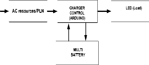
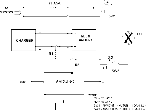
Fig. 2. Block diagram system
On the condition of PLN on, LED lighting system will get power source from PLN. Under normal conditions Charger Control will charge the battery and control the battery capacity, if the battery capacity is below the desired voltage threshold.
Charging will stop when the battery capacity meets the required voltage requirements (13.2 volts for each battery). At the time of PLN off, then the LED light will get power supply of DC power source.
It is necessary to test to know the lamp characteristics for AC and DC operation. For lamps that can operate on AC and DC sources then performed light intensity test of each LED lamp when operated at 220 volt AC voltage. The test results we use as a reference of the light intensity of each LED for DC voltage operation.
Tests LED lamps such as: LED brands Philips, Osram, Visicom and Opple, conducted at the Laboratory of Electrical Engineering, Faculty of Engineering, Udayana University.
The first test was carried out at 220 volt AC voltage, this test aims to obtain the light intensity of each LED lamp that will be used as the basis for determining the highest light intensity at the time of testing with DC voltage. The data taken from the test for each LED lamp are the data voltage (V), power (P), light intensity (I) and cos φ.
The first step is to raise the DC voltage starting from 0 volts slowly, and stopped when the LED lights start up. The next step is to increase the DC voltage and record the data: power, current, voltage, cos φ and intensity up to 220 volts.
The test is carried out on a box measuring 100 cm x 100 cm x110 cm with a whole black field. The position of the LED light is in the upper field of the box, while the luxmeter tool is placed on the bottom of the box.
The data for the measurement results of each LED lamp with variations of DC voltage are:
-
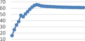
1) 9 watt Osram LED light.
The result of measurement with 220 volt ac voltage, the intensity produced by this LED is 125.4 lux. Operating with DC voltage as shown in Figure 4, the highest light intensity can be achieved at a working voltage of 220 volts DC with light intensity reaching 121.6 lux. The increase of light intensity of this LED lamp is linear.
3) 14 watt Osram LED light
The result of measurement with 220 volt AC, the intensity produced by this LED is 184.0 lux. Operating with DC voltage as shown in Figure 5, the highest light intensity can be achieved at 115 volt DC with light intensity reaching 191.2 lux.
Above 115 volt DC, the intensity of light generated has begun to decline and almost reaches an average of 180 lux.
9 watt ossram Led measurement result
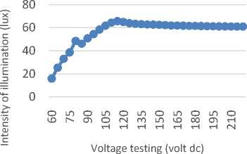
Fig. 3. Graph of 9 watt Led Osram lamp measurement with dc voltage
14 watt ossram Led measurement result
Voltage testing (volt dc)
The result of measurement with AC voltage 220 volts, the intensity of light produced by LED is 61 lux. Operating with a DC voltage such as Figure 3, the highest light intensity can be achieved at a 115 volt DC with 65.9 lux light intensity.
Above 115 volt DC, the intensity of light generated has begun to decline and almost reaches an average of 60 lux.
-
2) Philips 12.5 watt LED light
Fig. 5. Graph of 14 watt Led Osram lamp measurement with dc voltage
The intensity of light test result of voltage of AC and DC can be seen in Table I.
TABLE I
The Highest Light Intensity of Led Lamps with Dc Voltage
AND 220 V AC
12.5 w phillips Led measurement result
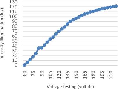
Fig. 4. Graph of 12.5 watt Led Philips lamp result with dc voltage
|
No |
LED light |
Rating Voltage (Vdc) |
Light intensity on VDc (lux) |
Light intensity on VAc (lux) |
|
1 |
9 W Osram |
115 |
61 |
61 |
|
2 |
7 W Opple |
220 |
46.1 |
46.9 |
|
3 |
12.5 W Philips |
220 |
121.6 |
125.4 |
|
4 |
14 W Osram |
115 |
191.2 |
184.0 |
D. System Applications
This equipment is used as a DC power source to provide power supply loads LED lights as illumination lamps. The placement of this equipment is best operated close to the lighting loads.
MCB 1
Voltage sensor
Fig. 6. Wiring diagram LED lighting system as illumination lamp
Figure 6 shows the wiring diagram of the LED lighting system. In operation using two operating systems, the operation on the condition of electrical power PLN on and operation on the state of the electric power PLN off.
-
1) Operating system with PLN power source on
If PLN power on condition, then LED lamp will get power supply from PLN power source, so light will be on. In this condition, the Arduino control system will also control the voltage capacity of the multi battery (using 10 batteries with total voltage at fix condition is 128 volts). Arduino is set to control the battery with a voltage condition between 70% for the lower limit, and 100% for the upper limit, meaning that if the multi voltage battery is under stress conditions below 80%, then Arduino will command R1 (relay 1) to charge the series battery to full (100% voltage condition).
If the battery charge reaches 100% (multi volt battery voltage 128 volt) then Arduino will reordered relay R1 to disconnect charger so that battery charging stalled. On the condition of PLN on, PLN will supply power for charger and LED light.
-
2) Operating system with power source PLN off
If the PLN power source is off, then the power flow from the PLN will be replaced with the power flow from the multi battery (DC power supply) so that the LED lights will remain on.
To maintain the life time of multiple batteries need to be controlled to determine the lower limit of the working voltage of the multi battery. In this system the lower limit of the working voltage of the multi battery set at 70% of the nominal voltage of the multi battery is more or less for a working voltage of 90 volts DC. If the multi voltage battery conditions are below 70%, then the Arduino will order relay 2 (R2) to disconnect the battery.
From Figure 6 it can be seen that switch over change process is done by switch (SW1) and (SW2). While the
charging process is done by relay 1 and relay 2 (R1 and R2) which are always controlled by Arduino micro controller.
In this test voltage is given as 13 Volt because it is usually set 110% - 115% of the nominal voltage battery and the current given following the amount of current that comes from electricity PLN. Charging occurs when the voltage on the battery is below the specified voltage.
The load to be operated is 14/9 watt LED, battery as power source used 10 units with the capacity of each 12,8 V, 7 AH. Long operation of lamp can be seen in Table II:
TABLE II
The Ability of The System to Back Up The Load
|
No |
LED light |
Power (Watt) |
Load current (A) |
Long Operation (Hour) |
|
1 |
10 x 9 watt |
90 |
0.703 |
9.953 |
|
2 |
10 x 14 watt |
140 |
1.093 |
6.404 |
|
3 |
15 x 9 watt |
135 |
1.055 |
6.635 |
|
4 |
15 x 14 watt |
210 |
1.641 |
4.266 |
|
5 |
20 x 9 watt |
180 |
1.406 |
4.979 |
|
6 |
20 x 14 watt |
280 |
2.188 |
3.199 |
From the research that has been done, it can be concluded:
-
1) 27 bulb LED lamps tested can be operated on AC or DC voltage. At the operation of DC voltage, each lamp has a variable operating voltage that is, for Osram LED operating voltage of 60-220 volts, the highest light intensity is at 115 volt working voltage. For opple LED operating voltage of 50-220 V, the highest light intensity at 220 volt voltage. Phillips LED working voltage of 60-220 volts, with the highest intensity at 220 volt working voltage.
-
2) The operating system is the DC power source of the multi battery will be charged by the Charger during normal operation by: the controller system will command the relay R1 to close when the battery voltage is below 70% of the nominal voltage, and reopen when the voltage has reached 100 %. To keep battery life time, Arduino will also order relay R2 to unlock when multi battery voltage is below 70%.
References
-
[1] Abdullah Iskandar, Agus Supriyadi, “Evaluate the use of LED lamps instead of conventional lamps”, Journal of Electrical Engineering, ISSN 2502-0986, Electrical Engineering Study Program of Lamongan Islamic University.
-
[2] Jimi Harto Saputro, Tejo Sukmadi, Karnoto, “Analyzing the use of LED lights at home lighting”,Transmission 15 (1), 2013, Department of Electrical Engineering Undip
-
[3] Khisbulloh, W.2011. The Basic Theory of Lighting. http://power-system.blogspot.com/2011/06/instalasi- penerangan-teori-dasar.html. Retrieved on November 27, 2011.
-
[4] Mardi Wasono, 2012, "Effect of light intensity of practicum room in reading of component color ring (resistor based on K3 standard)"
Instrumentation Service Unit, Department of IKE - FMIPA UGM Yogyakarta.
-
[5] Muhaimin.2001. Teknologi Pencahayaan. Bandung: Refika
-
[6] Riyan Masjanuar1, Eru Puspita, Taufiqurrahman, "Dimmer lamps in room lighting using LEDs equipped with automation and emergency" Electrical Engineering-PENS-ITS Surabaya
-
[7] SNI 03-6197-2000, "Energy conservation in lighting system" ICS 91.160.01 BSN (National Standard Body)
Discussion and feedback