Analysis Grounding System as Building Equipment Security Udayana University Denpasar
on
Journal of Electrical, Electronics and Informatics, Vol. 1 No. 2, September 2017
9
Analysis Grounding System as Building Equipment Security Udayana University Denpasar
I G. N. Janardana1*, W. Arta Wijaya2, Cok Gede Indra Partha3 and N. Budiastra4
-
1,2,3,4 Electrical Engineering Department Faculty of Engineering, Udayana University Badung, Indonesia
Abstract—Grounding system is one of the components in building equipment security. To fulfill the operational continuity of electronic equipment in Faculty of Engineering, Udayana University, Denpasar, a grounding system with a ground resistance of ≤ 3 ohms is required to be installed. The aim of this study is to find out the characteristics of grounding system to secure the equipment in the building around the research location, with ground resistance of ≤ 3 ohms and it is expected to be beneficial to use as a reference in grounding system installation as well as. According to the measurement results at the research location, it is found that the soil resistance value is equal to 0.23 ohms, where the soil resistivity (ρ) is 28.89 Ohm-meters. There are some results analysis obtained in ground resistance value of ≤ 3 Ohm. Those are 1) grounding system type 1 rod where minimal depth installation of the electrode is 14 meters with ground resistance value of 2.6751 ohms; 2) grounding system type two rod with s < L, it is obtained that each depth is 8 meters with distance of 2 meters between electrodes, where the ground resistance value is 2.4940 ohms. In the installation of two electrodes with s > L, it is gained that the depth of each electrode is 6 meters where the distance between the electrodes is 8 meters and the ground resistance value is 2.8718 ohms. By applying the plates type grounding system with 3 meters in length, 1 meter in width, and 2 meters in installation depth is gained 2.8431 ohms ground resistance value. Furthermore, by applying grid type grounding system with 2 meters in length h = 2,5 meters in depth, A = 4 meters in width and the total length of the electrode diameter 1 cm is 504 meters, it is obtained 2.0978 ohms ground resistance value.
Index Terms— Grounding system, equipment security.
-
I. Introduction1
Grounding system is one of the important factors in the equipment protection on the electrical power system during disturbance caused by over current and over voltage. The grounding system should have the smallest possible ground resistance value or ≤ 3 ohms as standard requirement for equipment safeguards. Soil texture is one parameter that significantly affects the ground resistance value and the ground resistance stability. Therefore, in this research will focus on soil resistance value (R) in order to get soil resistivity value (ρ). Then, that will be applied in order to analyze and find out grounding systems characteristic, such as one rod, two rods, plate system, and grid system.
Faculty of Engineering, Udayana University at PB. Sudirman Street Denpasar with sandy loam soil texture is chosen as object research since the equipment in this
building often got disturbance due to less optimal works of its grounding system. Its ground resistance value is 9 Ohms which is not appropriate as the standard one. The currently installed grounding system, type one with ground resistance value around 9 Ohms is still much larger than the allowable standard of ≤3 ohms. If it is left continuously it will endanger the existing equipment inside the building including the surrounding human if at any time there is disturbance by over current and over voltage.
-
1. The research of Janardana, to obtain the value of grounding resistance ≤3 ohms on the soil location of Faculty of Engineering Unud Denpasar with clay texture, when using one electrode must be planted with a minimum depth of 13 meters diameter electrode 1.2 centimeters [1].
-
2. Measurement result of ground resistance in panel Building A Faculty of Engineering, Udayana University, PB. Sudirman Street, Denpasar on May 2014 shows that the value of ground resistance is 6 ohms.
π 4Z 4Z S S2 S' 1
⅛ = ^—Γ ^n — + ^^7^^ + 77^--T +---F+.....
^2 4^4 a S 2L IW2 512Z,
……………………(3)
for S < L
S: the distance between the two electrodes (meters).
The grounding system is installed to drain current and overvoltage to the ground caused by lightning or internal disturbance of the electrical system, therefore both the system and human surrounding that area can be protected from the danger [2], [3], [4], [5].
-
1) Rod Electrode
The number of rod grown is adjusted to the size of the required ground resistance value or soil grounding type[6] .
-
2) Strip Electrode
This grounding electrode is used in places where it has high soil resistanceor soil resistivityand rocky and solid soil conditions.
-
3) Plate Electrode
It is a grounding elctrode that has plate-shaped and grown horizontal or vertical with diameter depth from the center of the surface plate [7].
-
a. Vertical Installed Electrode Type Grounding System (Rod Type Grounding System)
This type of grounding system is applied by placing electrode rods into the ground perpendicularly. Grounding by installing electrode vertically (rod) is not suitable for rocky soil or too solid soil. The equation for rod type grounding is [8] :
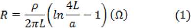
R = Ground Resistance (Ω)
= Soil resistivity (Ω-m)
L = Electrode length (Ω)
a = Electrode radius (Ω)
= coefficient of combination
-
b. Two Perpendicular Electrode Rods into the Ground
Two cylindrical electrode rods, length L which is installed perpendicular to the ground with the distance between the two electrodes is S [3].
The formula of soil resistance for two electrode rods installed perpendicular into the ground is:
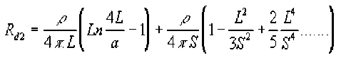
………………….(2) for S > L
-
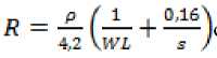
c. Plate Type Grounding System
Plate-shaped electrode is used in this grounding system. The ground resistance equation of this type grounding system is [7] :
(4)
= Soil resistivity( ohm – meter )
R = Ground resistance (ohm)
W = Plate width (cm)
L = Plate length (cm)
S = Installation depth (m )
-
d. Grid Type Grounding System
Grounding resistance with grid system can be calculated using the standard equation of IEEE std 80/2000 as follows [9], [10] :
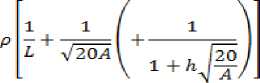
Rg = Ground resistance ( Ω )
ρ = Soil resistivity( Ω )
h = Conductor installation depth ( m )
L = Total conductor length ( m )
-
D. Soil
-
a. Soil Resistivity
Soil resistivity value in a finite depth depends on several factors as follows:
-
1. Soil type: clay, sandy, rocky and others.
-
2. Soil layer: layered with different resistance or uniform.
-
3. Soil moisture.
-
III. Research Methods
The research was conducted at Faculty of Engineering, Udayana University at PB. Sudirman Street Denpasar from July to October 2016.
In order to collect the data, there are several measurement steps which can be presented as following steps:
-
1) Preparing the components of the Earth Tester gauge to be used in the measurement
-
2) Installed 3 auxiliary pegs with 40 centimeters in length per each peg for the ground surface and one peg also 40 cm in length for the measured peg to obtain the soil resistivity value according to the measuring instrument catalog.
-
3) Installation or connection of cables on each rod with
the same distance between rods is 20 meters.
-
4) Connecting the connecting cable to the measuring equipment terminal (E, Es, S, H).
-
5) If the cable is fully connected, then do the measurement by first opening the switch E and Es
-
6) The measurement is begun by pressing the switch on the RE upwards.
-
7) Measurement of soil resistance is done automatically.
-
8) Entering the measurement results on the soil resistivity formula, ρa = 2π . a . R. Therefore, it will be obtained the soil resistivity required.
-
9) The measurement of soil resistivity used as analytical data is done on the same condition at 8 a.m., 10 a.m., 12 p.m., 2 p.m., and 4 p.m. during 5 days in the same location in order to keep the validity of the measured value. In addition, the measurement is done for 3 months.
The measurement data were analyzed by the calculations as in equations (1), (2), (3), (4) and (5). Specifically for rod type one rod and two rod s <L and two rod s> L) was tested by changing the diameter of rod into 1 cm, 1.2 cm and 1.5 cm. The result of the analysis is to obtain the characteristics of each type of grounding system.
The soil at Faculty of Engineering, Udayana University at PB.Sudirman Street Denpasar has loam soil texture to sandy.
In accordance with the measurement result of 15 times measurement of soil resistivity, it got 28.89 Ω-meters. That can be obtained from soil resistance (R), 0.23 and the distance between the rod electrodes of 20 meters.
TABLE I
Result of Soil Resistance Measurements
|
No |
Day |
Time |
Soil Resistance Value (R) (Ω) |
Soil resistivity (ρ) (Ω-m) |
|
1 |
I |
8 a.m. |
0.23 |
28.89 |
|
2 |
10a.m. |
0.23 |
28.89 | |
|
3 |
12 p.m. |
0.23 |
28.89 | |
|
4 |
14p.m. |
0.23 |
28.89 | |
|
5 |
16 p.m. |
0.23 |
28.89 | |
|
6 |
II |
8a.m. |
0.22 |
27.63 |
|
7 |
10a.m. |
0.22 |
27.63 | |
|
8 |
12p.m. |
0.22 |
27.63 | |
|
9 |
14p.m. |
0.23 |
28.89 | |
|
10 |
16p.m. |
0.23 |
28.89 | |
|
11 |
III |
8.a.m. |
0.22 |
27.63 |
|
12 |
10a.m. |
0.22 |
27.63 | |
|
13 |
12.p.m. |
0.23 |
28.89 | |
|
14 |
14p.m. |
0.23 |
28.89 | |
|
15 |
16.p.m. |
0.23 |
28.89 |
|
16 |
IV |
8.a.m. |
0.23 |
28.89 |
|
17 |
10a.m. |
0.23 |
28.89 | |
|
18 |
12p.m. |
0.23 |
28.89 | |
|
19 |
14p.m. |
0.23 |
28.89 | |
|
20 |
16p.m. |
0.23 |
28.89 | |
|
21 |
V |
08a.m. |
0.23 |
28.89 |
|
22 |
10a.m. |
0.23 |
28.89 | |
|
23 |
12p.m. |
0.23 |
28.89 | |
|
24 |
14p.m. |
0.23 |
28.89 | |
|
25 |
14p.m. |
0.23 |
28.89 |
The soil resistivity used is the results of the largest measurement values:
-
p = 2π aR
p = 2x3.14x20x0.23
s
Based on the measurement data obtained on the soil resistivity, the object research has 28.89 ohm-meters soil resistivity value. To obtain the ground resistance value ≤ 3Ω is as follows:
Regarding to the calculation results of each type of grounding with equations (1), (2), (3), (4) and (5), to obtain the ground resistance value ≤3 Ohms is as follows [11] : 1) Installation of one electrode rod with 1.2 centimeters in diameter (electrode radius (a) = 0.006 meters) after 14 meters in depth, it is gained ground resistance value 2.6751 ohms. It has obtained ground resistance value ≤ 3 ohms.
-
2) Installation of two electrode rods with 1.2 centimeters in diameter (electrode radius (a) = 0.006 meters) after 8 meters in depth with distance of 2 meters between the electrodes, 2.4940 ohms is gained as ground resistance value. It has obtained ground resistance value ≤ 3 ohms as well as.
-
3) Installation of two electrode rods with 1.2 centimeters in diameter (electrode radius (a) = 0.006 meters) after 6 meters in depth with distance of 8 meters between the electrodes, it is gained ground resistance value 2.8718 ohms. It has obtained ground resistance value ≤ 3 ohms.
-
4) Installation of plate type grounding system must be installed with 3 meters in length, 1 meter in width, 2 meters in depth gains 2.8431 ohms of ground resistance value which has obtained ground resistance value ≤ 3 ohms.
-
5) Installation of grid type grounding system must be installed with total length of the electrode 504 meters, 2.5 meters in depth and 4 meters width gains 2.0978 ohms of ground resistance value (≤ 3 ohms).
The choice of grounding / installation of grounding type of the five types in the analysis and based on the characteristics of the analysis results of each grounding shall be adjusted to the available area. The installation process of grounding system requires extensive space for
excavation and drilling as well as measurement of results. The type one rod and two rod grounding systems can still be installed in narrow locations, whereas the plate and the grid types of grounding system requires a wider land area.
In accordance with the data analysis, it can be concluded that in sandy loam soil, in order to gain ≤ 3 ohms of ground resistance value, type one requires 14 meters in depth, type two rod S>L requires at least 8 meters in depth with the distance between the electrodes is 2 meters, type two rod S>L requires at least 6 meters in depth with the distance between the electrodes is 8 meters, plate type grounding requires plate 3 x 1 meter in size and finally the grid type requires 504 meters in total length, 2.5 meters in depth. The choice of grounding / installation of grounding type of the five types in the analysis and based on the characteristics of the analysis results of each grounding shall be adjusted to the available area. The type one rod and two rod grounding systems can still be installed in narrow locations, whereas the plate and the grid types of grounding system requires a wider land area.
Acknowledgment
It is our pleasant duty to thank a large number of people for their helps and supports that they have provided during the time we have been working on this research. First of all,we are grateful for the Almighty God, Ida Sang Hyang Widhi Wasa for establishing and blessing us in completing this research. On this occasion, we would like to extend our thanks and appreciation to LPPM Udayana University, Electrical Engineering Department Faculty of Engineering Udayana University, Research Team and all friends who helped this research.
References
-
[1] Janardana, IGN. 2016. Sistem Pembumian Tipe Rod Sebagai Pengaman Peralatan Ruang Studio Teknik Arsitektur Gedung B Fakultas Teknik Universitas Udayana Jalan PB. Sudirman Denpasar. Denpasar : PS Teknik Elektro Unud.
-
[2] Hutaruk.TS.1987, Pengetanahan Netral dengan sistem Tenaga dan Pengetanahan Peralatan. Jakarta: Erlangga.
-
[3] Saini, M., dkk. 2010. Pengembangan Sistem Penangkal Petir Dan Pentanahan Elektroda Rod Dan Plat Pada Laboratorium Teknik Konversi Energi Politeknik Negeri Ujung Pandang. Academia.edu. https://www.academia.edu/8536126/
-
[4] Simamora, J., dkk. 2016. Pengaruh Penambahan Asam Sulfat(H2SO4) pada Bentonit untuk Penurunan Nilai Tahanan Pentanahan. Bandar Lampung: ELECTRICIAN-Jurnal Rekayasa dan Teknologi Elektro., Volume 10, No. 1.
-
[5] Sutikno, dkk. 1997. External & Internal Grounding. Bandung: DIVLAT PT. Telkom.
-
[6] Widyaningsih, W.P. 2013. Perubahan Konfigurasi Elektroda Pentanahan Batang Tunggal Untuk Mereduksi Tahanan Pentanahan. EKSERGI Jurnal Teknik Energi., Vol : 9, No. 2 Mei 2013. 47-51.
-
[7] Syofian, A. 2013. Sistem Pentanahan Grid Pada Gardu Induk PLTU Teluk Sirih. Jurnal Momentum., Vol : 14, No. 1 Februari 2013.
-
[8] Nugroho, D. 2016. Konfigurasi Elektroda Batang Pada Sistem Pentanahan. Jurnal: Transistor., Vol : 6, No. 1. Juli 2006. 7-22.
-
[9] Rizal, Y., dkk, 2014. Analisis Kinerja Sistem Pentanahan PT. PLN (Persero) Gardu Induk 150 kV Ngimbang-Lamongan Dengan
Metode Finite Element Method (FEM). Surabaya: Jurnal Teknik POMITS 1-6.
-
[10] Yudha, D.O. dkk., 2015. Implementasi Sistem Pentanahan Grid Pada Tower Transmisi 150 kV( Aplikasi Pada Tower SUTT 150 kV Antara Gardu Induk Indarung Dengan Gardu Induk Bungus).e jurnal.bunghatta.ac.id., Vol: 5. No. 1. 2015.
-
[11] persyaratan umum instalasi listrik 2011(puil 2011). amandemen 1. Jakarta: Badan Standardisasi Nasional. ICS : 13.260; 91.140.50.
Discussion and feedback