Design an IoT Based Pratima Monitoring System
on
JURNAL ILMIAH MERPATI VOL. 11, NO. 2 AUGUST 2023
p-ISSN: 2252-3006
e-ISSN: 2685-2411
Design an IoT Based Pratima Monitoring System
I Made Aris Aditya Nugrahaa1, I Nyoman Piarsaa2, Kadek Suar Wibawaa3 aDepartment of Information Technology, Faculty of Engineering, Udayana University, Bukit Jimbaran, Bali, Indonesia, phone. (0361) 701806
e-mail: 1arisaditya.made@gmail.com, 2manpits@unud.ac.id, 3suar_wibawa@unud.ac.id
Abstrak
Pratima biasanya disimpan pada pura atau disimpan di kamar suci. Kurangnya penjagaan serta pengawasan menyebabkan mudah terjadi kasus pencurian dan kerusakan karena kebakaran. Diperlukan sebuah Sistem monitoring pratima berbasis Internet of Things untuk menghindari beberapa ancaman yang terjadi. Perangkat yang dibuat terkoneksi dengan internet untuk melakukan monitoring, dan melakukan kontrol perangkat monitoring agar pratima tetap aman. Sistem monitoring pratima berbasis Internet of Things diharapkan menjadi sistem pencegahan awal tindak pencurian serta kerusakan karena kebakaran. Hasil yang didapatkan yaitu semua fitur berhasil dijalankan. Nilai pengukuran sensor ultrasonik sebesar 11CM dan 16CM, sedangkan penggukuran penggaris sebesar 10.5CM dan 16CM. Suhu pada DHT22 70.50°C, serta nilai flame sensor 123. Sensor microwave mendeteksi gerakan, serta capture gambar disimpan pada firebase dan SD Card.
Kata kunci: ESP32-CAM, Internet of Things, Kontrol, Pratima, Monitoring
Abstract
Pratima is usually kept in temples or kept in sacred rooms. Lack of care and supervision causes easy cases of theft and damage due to fire. An Internet of Things-based pratima monitoring system is needed to avoid some of the threats that occur. Devices that are made connected to the internet for monitoring, and controlling monitoring devices so that Pratima remains safe. The Internet of Things-based pratima monitoring system is expected to be an early prevention system for acts of theft and damage due to fire. The results obtained are all the features successfully run. The measurement values of the ultrasonic sensor are 11CM and 16CM, while the ruler measurements are 10.5CM and 16CM. The temperature on the DHT22 is 70.50°C, and the flame sensor value is 123. The microwave sensor detects movement, and the image capture is stored on firebase and SD Card.
Keywords : Control, ESP32-CAM, Internet of Things, Monitoring, Pratima
Temples are sacred places of worship for Hindus, where almost all religious activities are carried out in temples. Each temple has several pratima which are symbols or objects that are revered and sacred. Pratima is a symbol or representation of a deity's manifestation, so pratima is considered a sacred object or heirloom that is worshiped and has high religious value[1].
Pratima is usually kept in the temple in every traditional village or it can also be stored in the sacred room. Pratima will be stored in the gedong simpen, and taken out when the religious activities are carried out. When there are no religious activities, the temple becomes deserted, and theft cases can easily occur due to a lack of guard. The theft of pratima occurs because the pratima itself has very high economic value, such as the age of pratima which reaches tens of years, and the materials that adorn the embodiment of pratima or other sacred objects are classified as very expensive[2]. In addition to cases of theft, due to the lack of activities at the temple, causes a lack of attention from the temple management. This lack of attention makes it vulnerable to damage caused by unexpected disasters such as fires. Therefore, a monitoring tool is needed to protect pratima to avoid this situation.
The solution to this problem requires an Internet of Things (IoT) device system as well as uses Android. Therefore, the idea was obtained to design an Internet of Things-based Pratima monitoring system to avoid some of the threats that occur to Pratima. IoT or Internet of Things is the concept of connecting machines, equipment and other objects with sensors and
actuators to obtain data, and collaborate to take action based on new information obtained independently [3]. The Internet of Things-based pratima monitoring system is expected to be an early prevention system for acts of theft and damage due to fire, so as to increase the sense of security for stored pratima.
This research method uses the software development life cycle (SDLC) method with the waterfall model. The SDLC method with a waterfall model is a method for creating or developing applications with sequential steps like a waterfall that flows gradually from top to bottom[4].
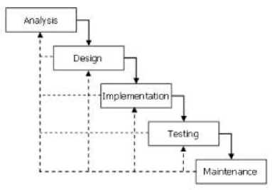
Figure 1. Research Method
Figure 1 shows the SDLC method with the waterfall model. The stages in the waterfall model are carried out sequentially to move to the next stage and are repeated until the stage is complete. These stages include analysis, design, implementation, testing, and maintenance.
An overview of the system is used to find out how the system flow will be made in research. The research design is generally described as follows.
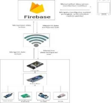
Figure 2. System Overview
Figure 2 shows an overview of the system created. The system created can monitor and control monitoring devices using an internet connection. The system workflow starts with the microcontroller processing the data received from several sensors. The data is then stored in the Firebase database using an internet connection. Users can view monitoring data, as well as carry out control of monitoring IoT devices so that they can make detections as desired.
The device will send a notification if it detects a measurement that does not match the device's previously set control data. In addition, the device that is made can capture images around the pratima storage area based on the duration of the shooting time that has been set.
-
2.2. Hardware Design
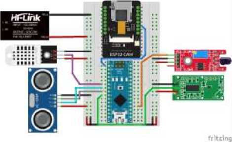
Figure 3. Hardware Design
The overall device design uses several devices as shown in Figure 3. Arduino Nano is used to process sensor data that is sent to the ESP32-CAM. ESP32-CAM is used to connect to the internet, as well as capture images. The power supply is used to get a power source for each device. In addition, several sensor devices are used, such as ultrasonic sensors to detect pratima position, DHT22 sensors to detect temperature and humidity, flame sensors to detect fire, and microwave sensors to detect movement. The design of the IoT device is made in the form of a prototype device, then it will be tested whether it has worked according to the expected results, and so that it can be developed even better later
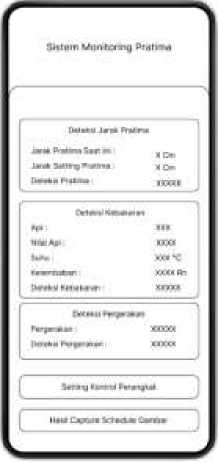
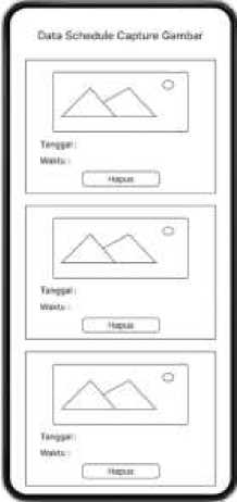
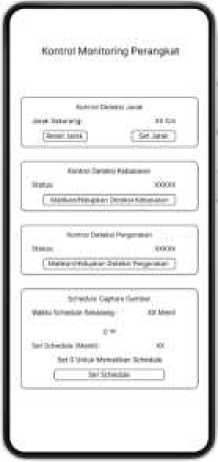
The design of the software is made as shown in figure 4. There is a monitoring display, as well as a monitoring device control display. The pratima monitoring displays include pratima distance detection, fire detection, and motion detection. The control display for the Pratima monitoring device contains several menus for controlling, such as distance detection control, fire detection control, movement detection control, and image capture schedule settings. In addition,
there is a display of the results of the image capture schedule which contains image capture data
Internet of Things is a concept for connecting objects or devices to be connected to each other by utilizing an internet connection, so that it can enable machines to collaborate to take actions based on new information obtained independently[5]. Internet of Things allows people and devices to be connected anytime, anywhere, with anyone using any line or network and any service[6].
Pratima is a sacred object or heirloom, which is a picture of a god or ancestor used for worshiping Ida Sang Hyang Widhi Wasa. Pratima in the temple acts as a medium between the people and God. Pratima has been used as a means of worship since before the establishment of the Singasari and Majapahit kingdoms, but now it is rarely done and only used as a sacred heirloom in every temple[1].
Arduino nano is a microcontroller that has the smallest size, is quite complete and can be used directly on a breadboard. Arduino Nano uses integrated circuits based on ATmega328 in version 3.x and ATmega168 in version 2.x as the core of the microcontroller [7]. The Arduino nano uses pin headers that allow for direct mounting on a breadboard and is equipped with a Mini-B USB connector.
The Arduino Nano has 14 digital pins with 6 supporting PWM outputs, and 8 analog pins. Arduino nano is the smallest Arduino microcontroller because it has dimensions of 45mm in length and 18mm in width and only 7 grams in weight.
The ESP32-CAM is a powerful and affordable microcontroller for developing Arduino projects with support for data transfer via WiFi and Bluetooth. The ESP-32CAM has a device size of 27x40.5x4.5 mm, is equipped with a camera module to capture images and has 10 GPIO ports to read input and control output based on the conditions of the program that has been made.
The ESP32-CAM is built on the basis of 40nm TSMC technology, is equipped with a 32bit dual-core processor, uses the ESP32-S chip, and has a slot for a microSD memory card. The ESP32-CAM microcontroller uses the OV2640 camera to obtain images of objects in the room. Image results can be stored on an SD card in JPEG format. To connect the module to a computer, an adapter from UART to USB is required[8].
Ultrasonic sensor is a sensor that works to detect the distance of an object based on sound reflection by reflecting ultrasonic waves[9].Ultrasonic sensors carry out measurements using 2 main components, namely a transmitter to emit ultrasonic waves with a frequency of 40 KHz, and a receiver to receive the results of reflected ultrasonic waves[10]. To get the measurement distance from the ultrasonic sensor, the equation is used
3 4 O /S
D is tance = Durati on—-— (1)
Where 340m/s is the speed of sound, then divided by 2 to get the length of the reflected wave from the sensor to the detected object[11].
DHT22 sensor or also known as AM2302 is a sensor used for temperature and humidity measurements[12]. The DHT22 sensor is a sensor with an output in the form of a digital signal on the data pin. Using a capacitive sensor and thermositor to measure the air temperature
around. The DHT22 sensor uses 4 pin feet to make measurements, namely the VCC, data, NC, and GND pins.
Flame sensor is a sensor that functions to detect the presence of a flame based on infrared light. The fire sensor works by detecting the presence of light or infrared light from a fire with a certain wavelength. The fire sensor can detect the presence of fire with a wavelength of 760nm – 1100nm with a measurement distance of less than 1 meter[13].
Microwave sensor is a sensor device that can detect movement. This sensor is almost similar to a PIR sensor which can detect human presence, but on a microwave sensor the detection is based on radar waves. Microwave Sensor RCWL-0516 is a microwave motion sensor, works by reading waves around. The reading distance from the movement that can be detected by the microwave sensor is up to 4 meters from the object's distance to the sensor[14].
Android is a Linux-based operating system developed by Google for use on several mobile devices. Android is an open source operating system, which makes it easy for developers to create an application[15]. Android application development itself can be done using the Android Studio IDE application, as well as using programming languages such as Java or Kotlin.
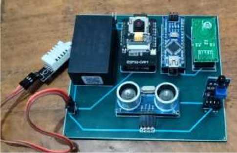
Figure 5. Hardware Implementation
Figure 5 is the realization of the implementation of the hardware that has been made. The devices used in this research are ESP32-CAM, Arduino Nano, microwave sensor (RCWL-0516), DHT22 temperature and humidity sensor, flame sensor, ultrasonic sensor (HC-SR04), and power supply (HLK-10M05). Devices made using Arduino Nano to read data from each sensor, then sent to the ESP32-CAM to connect to the internet and perform data processing and image capture
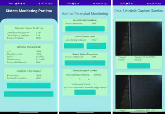
Figure 6. Software Implementation
Figure 6 is the realization of software design. The first display is the main view of the application which contains data from monitoring features in the form of pratima position detection, fire detection, movement detection, as well as 2 buttons to move to the device control display, and a button to view the results of the image capture schedule. The second display is the control display of the monitoring device in the form of control of fire detection, detection of pratima position, movement detection, and schedule of image capture. The third display is the result of image capture by an IoT device which contains image data, date and time of image capture. The data in the Android application is fully derived from data in the Firebase Realtime database
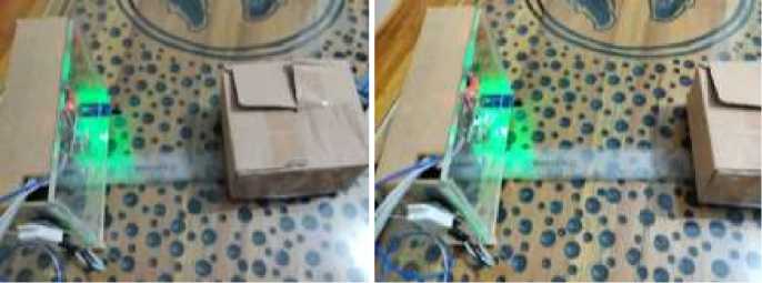
Figure 7. Pratima Position Detection Test
Figure 7 is a test of the pratima position detection. The pratima position detection test is carried out by moving objects from a pre-arranged distance, so that it gives a notification in the form of "Pratima Tidak Ditempatnya" if the user activates the pratima position detection feature. Notifications are also given if there are objects blocking the pratima with the sensor, this is because the distance measured is not the same as the distance that has been set. The test is carried out by placing an object at a distance of 10.5 CM in front of the IoT device, then the object is moved backwards to a distance of 16 CM
Slstem Moniuxlng
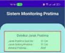
Figure 8. Pratima Position Monitoring Testing
Figure 8 is the result of monitoring the pratima position. The monitoring results obtained are the setting distance from the pratima position of around 11 CM. The distance from the initial position of the pratima measured by the ruler is 10.5 CM, and the distance from the displayed ultrasonic sensor is 11CM. The measurement distance from the position of the pratima when it is moved is 16 CM, and the displayed distance is 16 CM
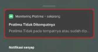
Figure 9. Pratima Position Notification Testing
Figure 9 is the notification display for the pratima position when it is turned on. The application will display a notification in the form of "Pratima is not in place", as well as a description of the notification in the form of "Pratima is not in place or has been moved".

Figure 10. Pratima Position Control Testing
Figure 10 is a display of the pratima position control. There are 2 buttons, namely the reset button to turn off the pratima position detection and set the detection distance to 0, and the distance setting button to activate the pratima position detection and adjust the position distance according to the current pratima distance. As seen in the picture above, pratima detection is activated with a position distance that is set at about 11 cm.
Table 1. Pratima Position Detection Feature Testing
|
No |
Feature |
Description |
Result |
|
1 |
Monitoring Pratima's Position from ultrasonic sensors |
Sends and displays ultrasonic sensor data in cm units |
Success |
|
2 |
Pratima Position Detection Control |
Set the distance detection from the pratima position based on the user's settings |
Success |
|
3 |
Pratima Not In Place Notification |
Gives notification of pratima out of place if pratima position detection is enabled |
Success |
Table 1 is the result of testing all features of the pratima position detection. Based on the results of the tests carried out, all the features of the pratima position detection were successfully carried out
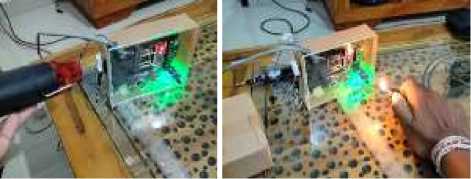
Figure 11 is a test of the fire detection. Fire detection testing is carried out by spraying hot temperatures, and lighting a fire using matches, so that the IoT device will detect high temperatures and the presence of fire. The system will provide a notification in the form of "Fire Detected" if the user activates the fire detection feature.
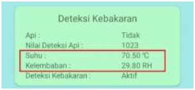
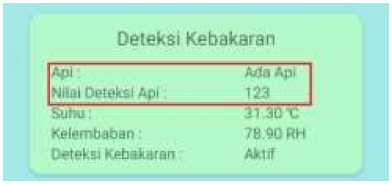
Figure 12. Fire Monitoring Testing
Figure 12 is the result of fire detection monitoring. The results obtained are a temperature value of 70.50°C when spraying hot air, and a humidity value of 29.80 RH by the DHT22 sensor, and a fire value of 123 with a fire status of "Ada Api" when lighting a fire.

Figure 13. Fire Notification Testing
Figure 13 is the appearance of a fire notification when it is turned on. the android application will provide a notification if a high temperature is detected in the form of "Terdeteksi Api", with the description "Terdeteksi Suhu Tinggi Disekitar Penyimpanan Pratima". In addition, the Android application will also provide a notification if a fire is detected in the form of " Terdeteksi Api", with the description "Terdeteksi Api Disekitar Penyimpanan Pratima".
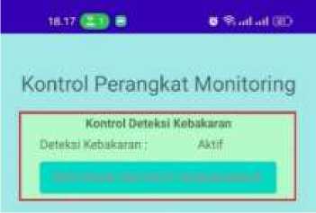
Figure 14. Fire Control Testing
-
Figure 14 is a display of the fire detection control, where there is a button to turn on/off fire detection. IoT devices will provide notifications on the android application when the user activates fire detection.
Table 2. Fire Detection Feature Testing
|
No |
Feature |
Description |
Result |
|
1 |
Monitoring of fire from flame sensor |
Send, as well as display data from flame sensor measurements |
Success |
|
2 |
Monitoring Temperature and Humidity from the DHT22 sensor |
Send, as well as display data from DHT22 sensor measurements |
Success |
|
3 |
Fire Detection Control |
Setting Detection in the form of activating or deactivating fire detection based on the user's settings |
Success |
|
4 |
Fire Detected Notifications |
Provides notification when a fire is detected by a flame sensor or dht22 if fire detection is activated |
Success |
Table 2 is the result of testing all the features of fire detection. Based on the results of the tests carried out, all the features of fire detection were successfully carried out
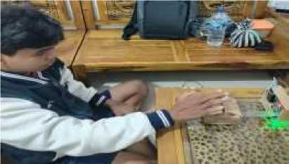
Figure 15. Motion Detection Testing
-
Figure 15 is a test of motion detection. Testing is carried out by moving in front of the sensor device, so that the sensor detects movement. The IoT device will provide a notification in the form of "Terdeteksi Pergerakan" on the android application, if the user activates the control of motion detection. Movements that are detected such as walking around the IoT device, or moving for a long time, around more than 1 second in front of the IoT device.

Figure 16. Motion Monitoring Testing
-
Figure 16 is the monitoring result of motion detection. The monitoring obtained is that the android application will display movement status in the form of "Bergerak" when movement is detected by the microwave sensor
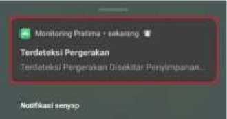
Figure 17. Motion Notification Testing
-
Figure 17 is the movement notification display when it is turned on. the android application will provide a notification in the form of "Terdeteksi Pergerakan" with a description in the form of "Terdeteksi Pergerakan Disekitar Penyimpanan Pratima", when the microwave sensor detects movement

Figure 18. Motion Control Testing
-
Figure 18 is a display of the fire detection control, where there is a button to turn on/off motion detection. If the user activates motion detection, the IoT device will provide a notification when movement is detected by the sensor device
Table 3. Motion Detection Feature Testing
|
No |
Feature |
Description |
Result | |
|
1 |
Movement from the sensor |
monitoring Microwave |
Sending, as well as displaying data from the detection of microwave sensors |
Success |
|
2 |
Motion control |
detection |
Setting Detection form motion detection by enabling or disabling based on the user's settings |
Success |
|
3 |
Motion Detected Notifications |
Provides a notification when motion is detected by the microwave sensor if motion detection is enabled |
Success | |
Table 3 is the result of testing all features of motion detection. Based on the results of the tests carried out, all features of the motion detection were successfully carried out
-
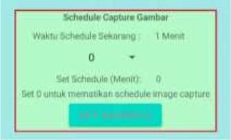
Figure 19 is a test of the image capture schedule. Testing of the image capture schedule is carried out by setting the time of the image capture schedule. Users can set the duration according to their needs, starting from 1 minute, 5 minutes, 10 minutes, 15 minutes, 30 minutes and 60 minutes.

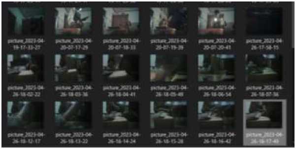
Figure 20. Image Capture Schedule Display Testing
-
Figure 20 is the result of the image capture schedule, where the application will display images from the image capture schedule that was carried out. Scheduled image capture results are also stored on the SD Card in the ESP32-CAM.
|
Table 4. Image Capture Schedule Feature Testing | |||
|
No |
Feature |
Description |
Result |
|
1 |
displays image scheduling data |
Displays a list of image data from the image capture schedule |
Success |
|
2 |
Set the Schedule Picture duration |
Set the duration of the shooting schedule based on the desired minutes, or turn off the image capture schedule based on the user's settings |
Success |
Table 4 is the result of testing all the features of the image capture schedule. Based on the results of the tests carried out, all the features of the image capture schedule were successfully carried out
The results of the IoT-based Pratima Monitoring System Design made are that all existing features have been successfully implemented, where the system created can monitor and control devices, provide notifications, and schedule image capture. The results of the detection of the pratima position from the ultrasonic sensor detect a distance of 11 CM and a distance of 16 CM when the object is moved, and the value of the measurement by the ruler is 10.5 cm and the distance when the object is moved is 16 CM. The results of the fire detection were successful in detecting a high temperature of 70.50 degrees by the DHT22 sensor and a fire value of 123 on the flame sensor, motion detection was successful in detecting movement when there was movement by the microwave sensor, and the device successfully scheduled image capture and stored on firebase and SD Card.
References
-
[1] I. Wayan Sukadana, “Desain Sistem Kontrol Keamanan Pratima dan Benda Pusaka
Berbasis sms Gateway I Wayan Sukadana,” in Pengembangan Insfrastruktur dan Technopreneurship Untuk Meningkatkan Daya Saing Bangsa, Jul. 2017, pp. 97–105, doi: 10.21063/PIMIMD4.2017.97-105.
-
[2] I. G. N. O. P. Setiawan, “Tindak Pidana Pencurian Benda Sakral dalam Putusan
Pengadilan di Wilayah Hukum Pengadilan Tinggi Bali,” J. Cakrawala Huk., vol. 9, no. 1, pp. 79–88, 2018, doi: 10.26905/idjch.v9i1.2618.
-
[3] I. G. S. S. Putu, I. N. Piarsa, and K. Suar Wibawa, “Internet of Things: Control and
Monitoring System of Chicken Eggs Incubator Using Raspberry Pi,” Int. J. Internet Things, vol. 7(1), no. 1, pp. 16–21, 2018, doi: 10.5923/j.ijit.20180701.03.
-
[4] H. Gunawan and A. K. H. Saputro, “Pemanfataan Aplikasi Mobile Untuk Mempercepat
Pencarian Tempat Indekos Berbasis Android,” J. Muara Sains, Teknol. Kedokt. dan Ilmu Kesehat., vol. 1, no. 2, pp. 85–96, 2018, doi: 10.24912/jmstkik.v1i2.1454.
-
[5] P. Denanta Bayuguna Perteka, I. N. Piarsa, and K. S. Wibawa, “Sistem Kontrol dan
Monitoring Tanaman Hidroponik Aeroponik Berbasis Internet of Things,” J. Ilm. Merpati (Menara Penelit. Akad. Teknol. Informasi), vol. 8, no. 3, p. 197, 2020, doi:
10.24843/jim.2020.v08.i03.p05.
-
[6] D. Sasmoko and D. Bachtiar, “Intelligent Baby Box Based on IoT to Observe Room
Temperature and Baby Crying,” Lontar Komput. J. Ilm. Teknol. Inf., vol. 9, no. 3, p. 114, 2018, doi: 10.24843/lkjiti.2018.v09.i03.p01.
-
[7] J. Asmi and O. Candra, “Prototype Solar Tracker Dua Sumbu Berbasis Microcontroller
Arduino Nano dengan Sensor LDR,” JTEV (Jurnal Tek. Elektro dan Vokasional), vol. 6, no. 2, p. 54, 2020, doi: 10.24036/jtev.v6i2.108504.
-
[8] R. B. Salikhov, V. K. Abdrakhmanov, and I. N. Safargalin, “Internet of things (IoT)
security alarms on ESP32-CAM,” J. Phys. Conf. Ser., vol. 2096, no. 1, 2021, doi: 10.1088/1742-6596/2096/1/012109.
-
[9] K. S. Wibawa and P. Wirabuana, “Design and Implementation of Monitoring System
Automatic Water Level Reservoir Controller,” Int. J. Latest Eng. Res. Appl., vol. 03, no. 12, pp. 8–15, 2018.
-
[10] W. Wagino and A. Arafat, “Monitoring Dan Pengisian Air Tandon Otomatis Berbasis Arduino,” Technol. J. Ilm., vol. 9, no. 3, p. 192, 2018, doi: 10.31602/tji.v9i3.1414.
-
[11] B. Setyawan, S. Andryana, and W. Winarsih, “Sistem Deteksi Menggunakan Sensor Ultrasonik berbasis Arduino mega 2560 dan Processing untuk Sistem Keamanan Rumah,” J I M P - J. Inform. Merdeka Pasuruan, vol. 3, no. 3, pp. 15–20, 2018, doi: 10.37438/jimp.v3i3.183.
-
[12] I. G. M. N. Desnanjaya, A. A. G. B. Ariana, I. M. A. Nugraha, I. K. A. G. Wiguna, and I. M. U. Sumaharja, “Room Monitoring Uses ESP-12E Based DHT22 and BH1750 Sensors,” J. Robot. Control, vol. 3, no. 2, pp. 205–211, 2022, doi:
10.18196/jrc.v3i2.11023.
-
[13] I. W. Pande Agustiana Putra, I. N. Piarsa, and K. Suar Wibawa, “Sistem Pendeteksi Kebakaran Menggunakan Raspberry Pi Berbasis Android,” J. Ilm. Merpati (Menara Penelit. Akad. Teknol. Informasi), vol. 6, no. 3, p. 167, 2018, doi:
10.24843/jim.2018.v06.i03.p03.
-
[14] Q. Aini, U. Rahardja, H. Madiistriyatno, and A. Fuad, “Rancang Bangun Alat Monitoring Pergerakan Objek pada Ruangan Menggunakan Modul RCWL 0516,” J. Tek. Elektro, vol. 10, no. 1, pp. 41–46, 2018, doi: 10.15294/jte.v10i1.13731.
-
[15] M. Toby, S. Pratika, I. N. Piarsa, and A. A. K. A. Cahyawan, “Design and Build Wireless Relay with Electricity Monitoring Based on Internet of Things,” J. Ilm. Merpati (Menara Penelit. Akad. Teknol. Informasi), vol. 10, no. 1, pp. 34–45, 2022, [Online]. Available: https://ojs.unud.ac.id/index.php/merpati/article/view/78291.
Design an IoT Based Pratima Monitoring System (I Made Aris Aditya Nugraha)
91
Discussion and feedback