Improving Network Performance of IP PBX Based Telecommunication System
on
LONTAR KOMPUTER VOL. 11, NO. 2 AUGUST 2020
DOI : 10.24843/LKJITI.2020.v11.i02.p04
Accredited B by RISTEKDIKTI Decree No. 51/E/KPT/2017
p-ISSN 2088-1541
e-ISSN 2541-5832
Improving Network Performance of IP PBX Based Telecommunication System
Wardi1, Zulfajri Basri Hasanuddin2, Andani3, Jeffry Jo Salli4, and Andi Muhammad Syafaat5
Department of Electrical Engineering, Hasanuddin University, Makassar, Indonesia Jl. Perintis Kemerdekaan Km. 10 Makassar, Indonesia 1wardi@unhas.ac.id 2zulfajri@unhas.ac.id 3andani@unhas.ac.id
4jeffry12d@student.unhas.ac.id 5dsyafaat12d@student.unhas.ac.id
Abstract
IP-PBX based communication has become a human need in the era of technology. Some researchers design a wireless telecommunication system based on IP PBX using Raspberry Pi. The previous researches have small network coverage and problematic on the ability of the system to support multiple concurrent connections. Based on these problems, these research aims are to expand the coverage area and increase the number of concurrent calls. This study used Asterisk FreePBX for the media configuration of the servers. The clients: laptops and smartphone devices used Linkin and Bria softphone. The testing was conducted in terms of voice and video services in the form of signal strength, CPU performance of servers, and network performance parameters such as delay, jitter, and packet loss. The results obtained that the CPU performance of the servers for seven calls simultaneously is around 16.9% compared with previous research, at an average of 45%. Based on ETSI standards, the measurement of network performance parameters when communicating between clients outperform than previous research. The clients can communicate well up to 390 meters.
Keywords: IP-PBX, Raspberry Pi, ETSI, Coverage Area, CPU Performance
Telecommunication is an important thing in daily life. Even telecommunication can be considered as one of the basic needs of human in the era of technology. The development of technology, especially in the field of wireless communications, has made communication more effective and efficient. One of the most effective telecommunication technologies has been developing is an IP based communications network technology such as Voice over Internet Protocol (VoIP) [1][2][3]. VoIP is an IP based communication which allows internet connection can perform speech call directly. The analog speech data is converted into digital data, then packetized and transmitted over a packet-switched network [4]. There are some advantages to using VoIP. Some of them are the VoIP is cheaper than conventional telephone and more flexible because it can be installed on any Ethernet or IP address [5].
VoIP uses the Session Initiation Protocol (SIP) as a signaling protocol to support the exchange of messages among the endpoints. The main functions of SIP are to establish, modify, and end a program session relating to one or several clients [6]. The traffic management of the VoIP is managed by IP-based switching devices like IP-PBX. The IP-PBX has an ability to connect between IP phones via TCP/IP protocols on both LAN and Internet [7]. IP-PBX is implemented based on Asterisk. Asterisk builds a real-time connection for VoIP technology to realize the VoIP system, such as MGCP, SIP, SCCP, H.323 [8][9]. The Asterisk is managed by FreePBX. FreePBX is a GUI application that supports services such as voicemail, ring groups, call routing, on-hold music, and call queues [10].
Several researchers have observed IP based communications technology. The research in [11] measures the performance of the IP based communication using Raspberry Pi Model B. The
research uses several coded types for voice communications. The average CPU usage for seven calls simultaneously performs at about 45%. Other studies measure the performance parameters of communication networks by using Raspberry Pi 2 as a server [12]. The study proves that voice communications between clients can be done well up to a radius of 100 meters from the server. Research on [13] tests the coverage area of Raspberry Pi for voice and video transmissions. The tests are based on network performance parameters in terms of throughput, delay, jitter, and packet loss. The study obtains that communication between clients is a maximum of 200 meters.
All the previous researches have a limited coverage area and problematic on the ability of the server to handle concurrent calls. Based on these problems, this research designs an IP PBX based communication system to improve the performances of the network. This study also can be a reference, especially for multi-hop networks Raspberry Pi based.
The basic concept in designing this system is to provide IP PBX based communication services in the form of voice and video calls. The system uses two mini-computers, Raspberry Pi 3, as portable servers. Figure 1 shows the design of the flow diagram of the system.
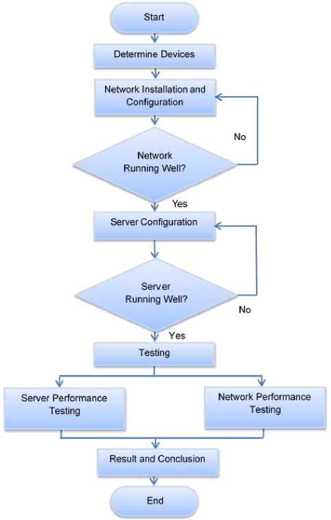
Figure 1. Diagram of System Design
Figure 1 shows that the research began by determining the devices, both software, and hardware. Then proceed with the installation and configuration of these devices to build a network system. After the installation and configuration process, testing is done to find out whether these devices can be connected to the network system. If the test is successful, then
continue with server configuration. Server configuration using Asterisk on FreePBX software through a web interface. After successfully configuring the server, the tests are conducted on server and network performances. The results are then analyzed in relation to the problem statement of this research. The results of the analysis are then concluded.
The software used in this research is Asterisk FreePBX, Softphone: Linphone and Bria, PuTTY, Web Browser, Wireshark, and Wifi Network Monitoring. The research also utilized some hardware devices for both servers and clients. The server consists of Raspberry Pi 3, MicroSD memory card, Network Adapter TP-Link WN722N, eight dBi Omni-directional Antenna TP-Link ANT2408CL, and Powerbank. The server can be seen in Figure 2. The clients comprise laptop HP Pavilion dm1-4000au, laptop Asus A46CB series, Smartphones Lenovo A6000 Plus, and smartphone Alcatel OneTouch Flash 2. Figure 3 shows the client devices.
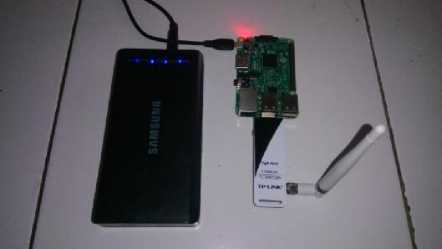
Figure 2. Server

Figure 3. Clients
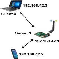
Network topology is the pattern of connecting structure between the nodes in a network. Topology deals with the mechanisms used to manage nodes in accessing the network to prevent conflict. This system uses a wireless network transmission medium on two servers and some clients. Therefore, the network topology used is the topology WLAN ESS mode. WLAN ESS mode is a set of two or more controllers where the clients can access mobile anyplace within the range covered by the multiple controllers. Therefore, the ESS mode can reach a wider area compared to a basic WLAN. The network topology is shown in Figure 4.
Client 1
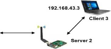
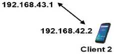
Figure 4. Network topology
There are some processes conducted in building the telecommunication system. The stages of the processes in detail can be seen in Figure 5.
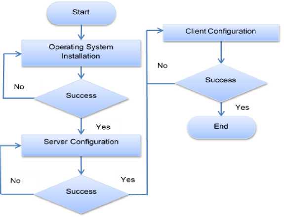
Figure 5. Stages of system design
Raspberry Pi uses a Linux-based operating system installed on a Micro SD memory card. The operating system used in this research is RasPBX, which is a lite version of Raspbian based operating system. The RasPBX includes the Asterisk and FreePBX software.
Servers are configured using Asterisk. The servers are controlled and managed by FreePBX through a web interface. The software sets several extensions as phone numbers for clients in the servers. The server also manages outbound routes and other settings to organize communications between clients. Some configuration parameters on FreePBX to control and manage the Asterisk can be seen in Table 1.
Table 1. Example for Asterisk configuration parameter on FreePBX
|
No. |
Parameter Setting Configuration Remarks Parameter |
|
1. |
Video codec H.264, MPEG4, Allow the codec for video H.263p, H.263 |
|
Voice codec a-law, u-law Allow the codec for audio Extension concurrent limit 20 Maximum concurrent call Client extensions for server 1 001 - 010 The extension to receive/make call Client extensions for server 2 101 - 110 The extension to receive/make call |
The stages of design on the client-side are: connecting the client on the access point, installing softphone, and registering on the server. The softphone for laptop is the Linphone, while for the smartphone is the Bria, which is the SIP-based softphone protocol. SIP-based softphone protocol is a software that allows clients to make telephone connections over the internet without a physical phone. The SIP protocol which performs signaling to establish, monitor, and terminate the connection when the communication end is carried out by the softphone.
Linphone configuration for a SIP account can be seen in Figure 6. The SIP configurations account includes a SIP identity and a SIP proxy address. The SIP identity is the client extension with IP gateway from the server while the SIP Proxy Address is the IP from the server gateway.
Configure a SIP account
Your SIP identity:
SIP Proxy address:
Registration duration (sec): Transport
Route (optional): Contact params (optional): AVPF regular RTCP interval (sec):
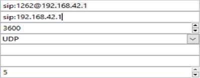
I I Publish presence information I I Enable AVPF
Figure 6. Linphone-configure a SIP account
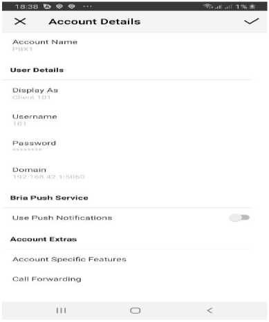
Figure 7. Bria account configuration
Figure 7 shows the account configuration for the client. The configuration includes Account Name, Display Name, Username, Password, and Domain. All the account configurations based on the account registered in FreePBX.
Measurements of network performance parameters of the telecommunication system were done in the line of sight (LOS) condition. The measurement parameters are signal strength, CPU performance of servers, and network performance parameters such as delay, jitter, and packet loss that refer to ETSI: TIPHON standard. The networks performances are measured by both Wireshark and Wifi Network Analyzer. The Wireshark can diagnose and record networking traffic in real-time while the Wifi Networks Analyzer is used to detect the signal strength of the Wifi signal on the system. The testing was conducted by creating three scenarios of communication. The scenarios are:
-
a. Communication between smartphones
-
b. Communication between smartphone and laptop
-
c. Communication between laptops
The voice calls use PCMA coded while the video calls use H.264 with display VGA (640 x 480 pixels).
The reliable performance on any network will guarantee the availability of services for clients. Therefore, it is needed to measure some parameters to know the network performance of the system. The parameters are jitter, packet loss, and delay [14][15][16]:
-
• Delay is an accumulation of delay times from sender to receiver. The recommendation
standard for delay by ETSI: TIPHON shows in Table 1.
-
• Jitter (delay variation) is the variation of arrival time intervals between packages in the
receiver device. The difference in the arrival time can be caused by some factors such as the capacity of the network, and congestion. Table 1 describes the recommendations of jitter by ETSI: TIPHON.
-
• Packet Loss is the overall lost packets when sending packet data between source and destination. The packet loss can be caused by collisions, the full capacity of the network or packet drops caused by the endless TTL packet. The standard of Packet Loss by ETSI: TIPHON can be seen in Table 2.
Table 2. ETSI: TIPHON Standard for QoS
|
Quality |
Delay (ms) |
Jitter (ms) |
Packet Loss (%) |
|
Perfect |
0 - 150 |
0 |
0 |
|
Good |
151 - 250 |
1 - 75 |
1 - 3 |
|
Fair |
251 - 350 |
76 - 125 |
4 - 15 |
|
Poor |
351 - 450 |
126 - 225 |
16 - 25 |
|
Bad |
>450 |
>225 |
>25 |
Table 2 describes QoS standards for Telecommunications and Internet Protocol Harmonization Over Networks (TIPHON) by European Telecommunication Standards Institute (ETSI). The table shows the five levels of quality in communication transmission. The highest quality of the networks is a perfect quality where the clients communicate normally over a network. The small delays (<251 ms), jitter (<76 ms), and packet loss (<4%) perform good communication between the clients. The quality of service of the network is degraded from perfect quality to bad quality as the values of the parameters increase.
The test was conducted to measure signal strength from server to server and from server to clients with various distances. The default four dBi antenna of the transmitter TP-Link wireless network adapter type TL-WN722N was replaced with an eight dBi antenna of TP-LINK type ANT2408CL in order to increase signal strength level. The measurements were done in Line of Sight condition. Figure 8 shows the topology of signal testing.
Testing every 10m (10-130m)
Server
Server/Client
Figure 8. Signal Testing
CPU performance testing uses 14 clients (7 concurrent calls). The client 1 to client 7 communicates with client 8 to client 14. The topology of the testing describes in Figure 9.
Server 1
Server 2

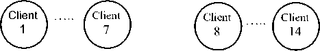
Figure 9. CPU Performance Testing
The performance parameter testing, the client, performs a call both voice and video communication alternately every 10 meters along 130 meters away. Figure 10 illustrates the measurement of the performance parameter of the system.
Server 1
Server 2
10 m
10m
Testing every 10m (10-130m)
v = 1m/s

Figure 10. Performance Parameter Testing
Figure 11 shows the results of the signal testing both from server to server and from server to clients (smartphone and laptop). The results show that the received signal strength reduces with the propagation distance. The farther the distance from the server 1, the lower the signal level generated. The figure shows that with the installation of an 8 dBi antenna, the signal level
up to a distance of 130 meters still reaches the value of -90 dBm. Based on the standard of RSII by ETSI [17], the signal level at -90 dBm performs fair quality but can still be acceptable. Therefore, based on the network topology in Figure 2, which implements two servers, the communication among the clients well connected on the network with the maximum transmission distance of 390 meters. The result is better than previous studies, which were about 100 meters [12] and 200 meters [13].
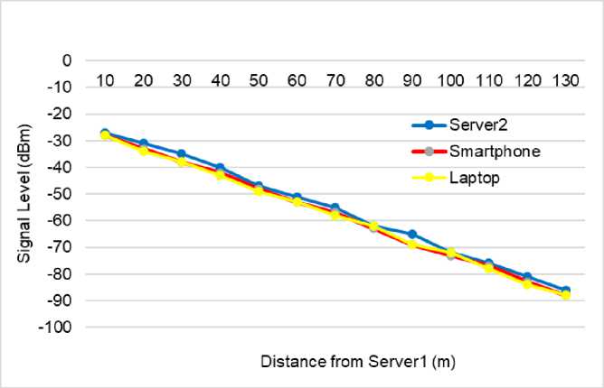
Figure 11. Signal Strength
The testing is done by doing multiple calls simultaneously, then observing the CPU performance level on the Raspberry Pi server. The test results can be seen in Figure 12. Figure 9 shows the CPU utilization increases consistently with the number of concurrent calls. The increasing CPU usage due to the CPU has more work to complete and serve the connection process requests. To reduce the workload of the server, the research uses two servers so that the server performance can be distributed. In general, the percentage of CPU utilization reaches the values at about 16.9% when seven calls are served concurrently by the servers. Figure 9 also shows that the research result 16.9% outperforms the previous research with CPU usage at around 45% [11].
50
45
40
35
30 co „ ≡ 25
5 20
5
0
Concurrent Call (Client)
Figure 12. CPU Utilization of Servers
Figure 13 and Figure 14 show respectively, the average delay for voice and video communication.
21,6
21,4
21,2
ω
E
CC 0
21
20,8
20,6
20,4
20,2
20
10 20 30 40 50 60 70 80 90 100 110 120
130
Distance (m)
-
Figure 13. Average Delay for Voice Communication
Figure 13 shows the voice communication at a distance between 10 and 130 meters from the server. The average delay varies between 20.22 - 22.46 ms.
-
a. Scenario A: the average value of delay ranges from 20.24 to 21.10 ms.
-
b. Scenario B: the average value of delay ranged from 20.56 - 22.46 ms.
-
c. Scenario C: the average value of delay ranged between 20.22 and 20.7 ms.
The results illustrated in Figure 13 describe that the three test scenarios show the average delay remains stable in the range of 20.22 - 22.46 ms. The research shows that the propagation delay does not significantly affect the value of voice communication delay at distances up to 130 meters.
55
50
45
40
35
30
25
20
15
10
10 20 30 40 50 60 70 80 90 100 110 120 130
Distance (m)
-
Figure 14. Average Delay for Video Communication
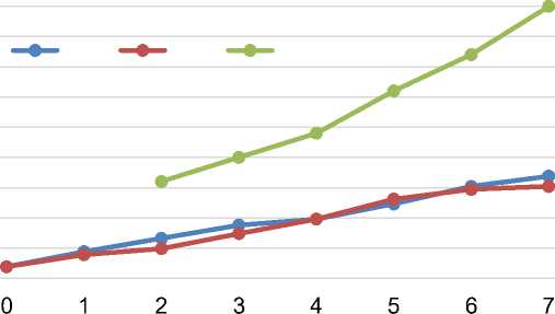
Figure 14 shows video communication with the communication distance from 10 to 130 meters from the server. The average delay varies between 25.28 and 50.42 ms.
-
a. Scenario A: the average delay ranged from 25.28 - 23.6 ms.
-
b. Scenario B: the average delay ranges from 27.72 - 30.1 ms.
-
c. Scenario C: the average delay ranged from 23,72 - 50,45 ms.
The delay that occurs in video communication at a distance from 10 to 130 meters shows no significant increase with increasing the distances. The average delay in 3 scenarios is between 25.28 and 50.42. The delay illustrates that up to a distance of 130 m, propagation delay in this study does not affect the quality of service of the systems.
Based on ETSI: TIPHON standards for delay [16], both voice and video communications can communicate well at a radius of 130 meters from the server. Therefore, the communication between clients can be done until a distance of 390 m.
Average jitter for voice communication is described in Figure 15, while for video communication in Figure 16.
17
15
13
11
9
7
—•—Scenario A —•— Scenario B —•— Scenario C
5
10 20 30 40 50 60 70 80 90 100 110 120 130
Distance (m)
-
Figure 15. Average Jitter for Voice Communication
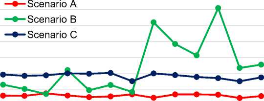
Figure 15 illustrates the voice communications at a distance between 10 and 130 meters from the servers. The average jitter ranges from 8.98 to 19.06 ms.
-
a. Scenario A: the average jitter ranges from 9.56 - 13.02 ms.
-
b. Scenario B: the average jitter ranges from 8.98 - 19.06 ms.
-
c. Scenario C: the average jitter ranges from 9.02 - 14.9 ms.
The average jitter for voice communication in 3 scenarios shows remain stable between 8.98 and 19.06 ms. The results of the average jitter indicate that the jitter does not reduce the network quality of the communications system up to a distance of 130 m.
50
40
30
20
10
—•— Scenario A —•—Scenario B —•— Scenario C
0
10 20 30 40 50 60 70 80 90 100 110 120 130
Distance (m)
-
Figure 16. Average Jitter for Video Communication
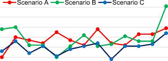
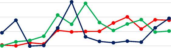
Figure 16 shows the video communication at a distance from 10 to 130 meters from the server. The average jitter varies between 13.48 - 46.3 ms.
-
a. Scenario A: the average jitter ranges from 13.48 - 16.36 ms.
-
b. Scenario B: the average jitter ranges from 38.12 - 37.9 ms.
-
c. Scenario C: the average jitter ranges from 31.65 to 46.3 ms.
The graphics show that video communication made by smartphone and smartphone (scenario A) has an average jitter smaller than communication from smartphone to laptop (scenario B) and laptop to laptop (scenario C). Scenario A has an average jitter at about 23 ms lower than the other two scenarios. The differences might be caused by the processing of data packets on the smartphone better than on the laptop.
Based on ETSI: TIPHON standards for jitter [16], both voice and video communications can communicate well at a radius of 130 meters from the server. Therefore, the communication between clients can be done up to a distance of 390 m.
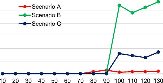
Figure 17 and Figure 18 illustrate the result of packet loss (%) testing for communication at a distance from 10 to 130 meters from the server. Figure 17 shows the voice communication at a distance of up to 130 meters from the server. The average packet loss varies from 0 to 0.28%.
-
a. Scenario A: the average packet loss from 0 - 0.06%.
-
b. Scenario B: the average packet loss from 0 - 0.06%.
-
c. Scenario C: the average packet loss appears from a distance of 110 m to 130 meters, which ranges from 0.24 to 0.28%.
The average packet loss for voice communication in all three scenarios is very small. Package loss in scenarios A and C show no significant increase in all distances. In scenario B, the packet loss increases sharply, starting at a distance from 100 to 130 m. The highest packet loss in scenario B is at a distance of 130 m, with a loss of the packets at around 0.28%.
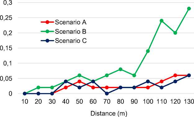
Figure 17. Average Packet Loss for Voice Communication
3,5
3
Distance (m)
Figure 18. Average Packet Loss for Video Communication
2,5
2
1,5
1
0,5
0
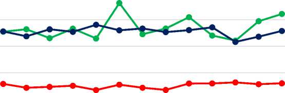
Figure 18 depicts the video communication at a distance of up to 130 meters from the server. The average of the packet loss varies from 0 to 3.72%.
-
a. Scenario A: the packet loss occurs when calling at a distance from 80 to 130 meters
from the server, which ranges between 0.06 - 0.1%.
-
b. Scenario B: the packet loss appears from the distance of 100 m to 130 m, where the
packet loss for about 0.64 - 0.86%.
-
c. Scenario C: at a distance between 100 and 130 m from the server, there is some packet loss, which ranges from 2.64 - 3.72%.
The graphic for video communication shows that the packet loss in scenario A is very small, where the highest packet loss is only about 0.1%. Likewise, in scenario C the highest packet loss is around 0.86% at a distance of 130 meters. Scenario B has a higher packet loss compared to 2 other scenarios, which is approximately 3.72%. However, packet loss is still in the range of good quality.
Based on ETSI: TIPHON standards for packet loss [16], the packet loss less than 4 % are categorized in good quality. Therefore, both voice and video communications can communicate well until a radius of 130 meters from the servers and 390 meters between clients.
This research has succeeded in designing an IP PBX-based wireless communication system with a wider covered area and better CPU performance of servers. The use of 8 dBi omnidirectional antennas and two servers increases the range of the covered area so that the clients can communicate well until 390 meters. The use of 2 servers can also distribute server workloads, thereby reducing CPU utilization of the servers. CPU usage reaches the values at about 16.9% when seven calls are served concurrently by the servers. Based on ETSI: RSII and TIPHON standards, communication testing up to 390 meters, QoS parameters such as delay, jitter, and packet loss, the telecommunication system meet good quality standards.
References
-
[1] I. Nedyalkov, G. Georgiev, and A. Stefanov, “Studying and Characterization of the Data
Flows in an IP-Based Network,” Int. J. Inf. Technol. Secur., vol. 11, no. 1, pp. 3–12, 2019.
-
[2] L. Hernandez and M. Ospina, “Scheme and Creation of a Prototype for the Supervision
of Lights and Electronic Devices with a PBX, using a WLAN Solution Based on IoT,” in 2019 IEEE Colombian Conference on Communications and Computing (COLCOM),
2019, pp. 1–6, doi: 10.1109/ColComCon.2019.8809159.
-
[3] J. P. B. López and Y. M. Pérez, “Integration of Asterisk IP-PBX with ESP32 Embedded
System for Remote Code Execution,” in The 2nd XoveTIC Congress, 2019, pp. 1–3, doi: 10.3390/proceedings2019021038.
-
[4] S. El Brak, M. Bouhorma, M. El Brak, and A. A. Boudhir, “VoIP Applications over
MANET: Codec Performance Enhancement by Tuning Routing Protocol Parameters,” J. Theor. Appl. Inf. Technol., vol. 50, no. 1, pp. 68–75, 2013.
-
[5] R. Narula and P. Aggarwal, “Performance Evaluation of RIP and OSPF in IPv6 Using
Opnet 14 . 5 Simulator,” Int. J. Tech. Res. Appl., vol. 2, no. 6, pp. 37–41, 2014.
-
[6] J.-C. Chen and T. Zhang, IP-Based Next Generation Wireless Networks. New Jersey:
John Wiley & Sons, Inc, 2013.
-
[7] S. Khan and N. Sadiq, “Design and Cofiguration of VoIP based PBX using Asterisk
Server and OPNET Platform,” in 2017 International Electrical Engineering Congress (iEECON), 2017, pp. 1–4, doi: 10.1109/IEECON.2017.8075808.
-
[8] F. Iseki, Y. Sato, and M. W. Kim, “VoIP System based on Asterisk for Enterprise
Network,” in International Conference on Advanced Communication Technology (ICACT), 2011, pp. 1284–1288.
-
[9] A. Robar, FreePBX 2.5 Powerful Telephony Solutions, 1st ed. Birmingham, Mumbai,
2009.
-
[10] P. Mahler, VoIP Telephony With Asterisk A Technical Overview of the Open Source
PBX, 2nd ed. USA: Signate, 2005.
-
[11] D. Peláez, J. A. Estrada, C. Tipantuña, and J. C. Estrada, “Performance Analysis of a Raspberry Pi Based IP Telephony Platform,” Rev. Politec., vol. 36, no. 1, pp. 72–77, 2015.
-
[12] P. V. and V. M. Deshmukh, “Implementing the VOIP Communication Principles using Raspberry Pi as Server,” Int. J. Comput. Appl., vol. 124, no. 4, pp. 34–38, 2015, doi: 10.5120/ijca2015905449.
-
[13] Wardi, A. Achmad, Z. B. Hasanuddin, D. Asrun, and M. S. Lutfi, “Portable IP-based Communication System using Raspberry Pi as Exchange,” in Proceedings - 2017 International Seminar on Application for Technology of Information and Communication (iSemantic), 2017, pp. 198–204, doi: 10.1109/ISEMANTIC.2017.8251869.
-
[14] F. Farid, S. Shahrestani, and C. Ruan, “QoS Evaluation of Heterogeneous Networks: Application-Based Approach,” Int. J. Comput. Networks Commun., vol. 8, no. 1, pp. 47– 60, 2016, doi: 10.5121/ijcnc.2016.8104.
-
[15] M. O. Ortega, G. C. Altamirano, and M. F. Abad, “Evaluation of the Voice Quality and QoS in Real Calls using Different Voice over IP Codecs,” in 2018 IEEE Colombian Conference on Communications and Computing (COLCOM), 2018, pp. 1–6, doi:
10.1109/ColComCon.2018.8466727.
-
[16] ETSI, “Telecommunications and Internet Protocol Harmonization Over Networks (TIPHON); General Aspects of Quality of Service (QoS),” 1999. [Online]. Available: http://www.etsi.org/deliver/etsi_tr/101300_101399/101329/02.01.01_60/tr_101329v0201 01p.pdf.
-
[17] ETSI, “Digital Enhanced Cordless Telecommunications ( DECT ); Compatibility with Cellular Technologies Operating on Frequency Block Adjacent to the DECT Frequency Band,” 2013. [Online]. Available: https://www.etsi.org/deliver/etsi_tr/103000_103099/ 103089/01.01.01_60/tr_103089v010101p.pdf.
113
Discussion and feedback