Design of Autonomous Quadcopter Using Orientation Sensor with Variations in Load Fulcrum Point
on
LONTAR KOMPUTER VOL. 10, NO. 2 AUGUST 2019
DOI : 10.24843/LKJITI.2019.v10.i02.p03
Accredited B by RISTEKDIKTI Decree No. 51/E/KPT/2017
p-ISSN 2088-1541
e-ISSN 2541-5832
Design of Autonomous Quadcopter Using Orientation Sensor with Variations in Load Fulcrum Point
Ratna Aisuwaryaa1, Fitra Marta Yonasa2, Dodon Yendria3
aComputer Engineering, Faculty of Information Technology, Andalas University Kampus Unand Limau Manis, Padang, Indonesia 1aisuwarya@fti.unand.ac.id
2fitramy13@gmail.com 3dodon@fti.unand.ac.id
Abstract
In designing the quadcopter, the main focus is stability and balance. Thus, in the more specific implementation, for example for aerial photography, a quadcopter can also be used as a load carrier. To be able to balance the quadcopter equipped with an orientation sensor on the controller, the orientation sensor includes a gyroscope sensor, accelerometer, and magnetometer. For this reason, it is necessary to have an autonomous stabilizer mechanism that can make the quadcopter stay in a stable and balanced condition even with the additional load. Furthermore, in this research, we will discuss how to determine the PID set points for quadcopter balance that can be tested on loads with different fulcrums. The test is limited to the condition of the quadcopter being hovered for pitch and roll angles. Based on the testing results, it can be concluded that there is a stability response in the Quadcopter. It can be seen from the RMS value obtained that it is by the steady-state tolerance of 2% -5% of the setpoint. Then, the Quadcopter can carry the maximum load with different fulcrums; 950g for fulcrum in the middle of the quadcopter, 580g for the load is placed 6 cm from the middle of the quadcopter, and 310g if the load is placed on one motor.
Keywords: Quadcopter, stability, PID, Orientation Sensor, fulcrum
Unmanned Aerial Vehicle (UAV)s are planes that do not require human operators in them, using aerodynamic forces to lift vehicles, can fly independently or be driven remotely, and can carry loads. One example of a UAV is a quadcopter. The quadcopter has the advantage of being able to fly in all directions, airing without a long runway, and moving on three axes. The quadcopter is used for various functions such as those can not be reached by humans such as monitoring road congestion, surveying and mapping, spy robots, and monitoring natural disasters. In designing the quadcopter, the main focus is stability and balance on the quadcopter [1]. The quadcopter must also be able to take orders and fly according to the instructions given; it will be fatal if it does not go as desired. To be able to balance the quadcopter equipped with an orientation sensor on the controller, the orientation sensor includes a gyroscope sensor, accelerometer, and magnetometer [2].
In the study with PID controls able to stabilize complex systems so that it has succeeded in making a quadcopter that can fly stably. Moreover, in the research [3] has succeeded in making a quadcopter that can stabilize itself against the x-axis, using fuzzy methods. In the two studies discussed the balance of the quadcopter only. Thus, in the more specific implementation of a quadcopter, for example for aerial photography [4][5][6], a quadcopter must be able to carry a camera, and besides that, a quadcopter can also be used as a load carrier. For this reason, it is necessary to have an autonomous stabilizer mechanism on the quadcopter that can make the quadcopter stay in a stable and balanced condition even with the additional load given to the quadcopter. Then this additional load will later have variations in fulcrum point so that a quadcopter system that can carry the load and maintain its balance to the load with a different load fulcrum point can be obtained.
Furthermore, in this research, we will discuss how to determine the set points for quadcopter balance and design a stable quadcopter that can be tested on loads with different fulcrums. The balance test is limited to the condition of the quadcopter being hovered for pitch and roll angles. The weight to be tested is 500g and 200g with three load points, namely in the middle position of the quadcopter, the second is between two quadcopter arms, and the third is on one of the quadcopter arms.
Proportional Integrative Derivative (PID) is a control system to determine the precision of an instrumentation system with the characteristics of feedback on the system. This PID control component consists of three types, namely Proportional, Integrative, and Derivative [7][8]. In a control system, there are several types of control actions, including proportional control, integral control, and derivative control. Each of these control actions has certain advantages, where the proportional control action has the advantage of rapid rise time, integral control action has the advantage of minimizing errors, and the derivative control action has the advantage of minimizing errors or reducing overshot/undershot. For this reason, in order to produce output with fast rise time and a small error, we can combine these three control actions into the PID control as in Figure 1.
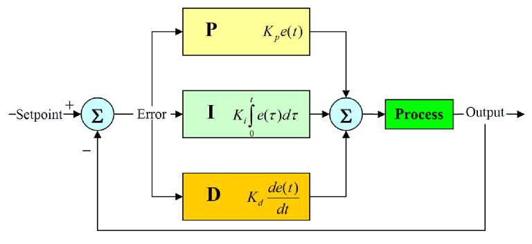
Figure 1. PID Control Block Diagram
The output value of the PID control is formulated as:
u (t) = Kpe(t)+ Ki ^ e ^d t + Kd ± e( t) (1)
Equation (1) describes the output value u(t), which is the sum of proportional gain (Kp), integral gain (Kι), and derivative gain (Ka), each of which is changed by error (e) in a specific interval (t).
The designed Quadcopter as in figure 2 consists of: (1). Brushless motor is a type of motor that has a permanent magnet construction (rotor) and a wire-bound polar stator [9]. Electrical energy is converted into mechanical energy by the influence of magnetic force between the permanent magnet and a polar stator. The number of magnetic poles in the rotor also affects the step size and torque ripple of the motor, (2) Electronic speed controller (ESC) interprets signals from the receiver and works to provide variations in motor speed. The signal on the ESC is a Pulse Width Modulation (PWM) signal, which means that to control the motor speed (RPM) the ESC varies the PWM signal according to the RC transmitter.
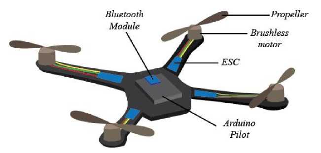
Figure 2. Quadcopter Design
-
(3) . Propeller produces lift. In Newton's Law of Lifts and deflection of the flow, lifts are generated due to air pressure and compressive forces from the wing area, that the pressure of the wing area does not produce a pure force, but a pressure difference is needed to produce a lift. (4). The Bluetooth module is used as a transmitter and receiver on a quadcopter. Bluetooth is a wireless communication protocol that works on 2.4 GHz radio frequencies [10]. The Bluetooth module used is the HC-05 type. (5). ArduPilot Mega is an electronic kit or an unmanned aerial vehicle electronic circuit board with ATMega328 as its microcontroller. Ardupilot Mega has an MPU-9250 IC as an orientation sensor. This sensor consists of a Motion Tracking 9-axis device that combines a 3-axis gyroscope, 3-axis accelerometer, 3-axis magnetometer and Digital Motion Processor (DMP) all in one chip package with a size of 3x3x1 mm [11].
Quadcopter diagram block can be seen in Figure 3.
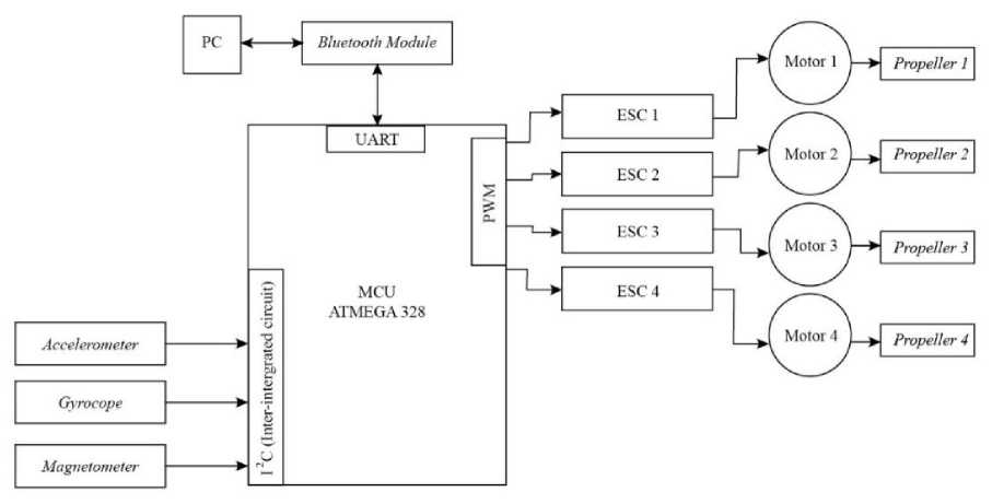
Figure 3. Block Diagram of Quadcopter Design
The quadcopter is controlled by computer via Bluetooth signal. Moreover, the Bluetooth module is connected to the Ardupilot so that the quadcopter can be connected to the computer. For balance on the quadcopter using the Accelerometer sensor, Gyroscope, and magnetometer. Then the sensor readings will be processed using PID controls and generated PWM. The PID control parameters, Kp, Ki, and Kd, are obtained from the simulation results. ESC functions to regulate motor speed. Each motor will rotate differently according to the results of processing in the PID control to produce a quadcopter that can fly stably. The motor will be connected to the propeller to produce lift on the quadcopter.
Motor speed will be influenced by orientation data taken by the sensor; if the orientation of the quadcopter is below the balance set point, the motor will be given additional power to move the motor so that the orientation of the quadcopter can reach the balance set point. If the quadcopter's orientation crosses the balance set point, the power supplied to the motor is reduced. Motor control is done by adjusting the power based on the PWM signal based on the PID control output and signal data sent to the Electronic Speed Controller (ESC). The system will continue to operate to correct the orientation of the quadcopter until the desired set point balance is obtained. Calibration set point balance stored in the Microcontroller program, when the system detects the orientation of the quadcopter is by the balance set point, the motor will maintain the orientation of the quadcopter.
The fulcrum of the test load is designed with a distance of one point to another of 5 cm. By placing the load at each different point, it will cause the quadcopter's condition to be tilted; this is where it is arranged so that the quadcopter can fly in a stable move even though it is given a load with a different fulcrum.
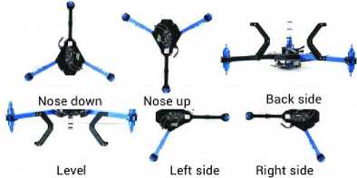
Figure 4. Setup to Determine the Setpoint Value
In Figure 4, the quadcopter position can be seen to get the setpoint value. Based on the results of this processing in Table 1, the set point values will be obtained for use by the PID control. The PID control parameters, Kp, Ki, and Kd, are obtained from the simulation results that have been made used in quadcopter so that the values obtained for controlling the speed of each motor to achieve a balanced state can be compared with the quadcopter in simulation.
Table 1. Set Point Value of Quadcopter
|
Position |
Angle |
Accelerometer |
Gyroscope | |||
|
Roll |
Pitch |
X |
Y |
X |
Y | |
|
Level |
0.0008 |
0.9 |
2 |
0 |
1 |
0 |
|
Left Side |
-89.9 |
1 |
22 |
998 |
4 |
0 |
|
Right Side |
90 |
1 |
21 |
-998 |
1 |
0 |
|
Nose Up |
180 |
89 |
1000 |
-2 |
4 |
1 |
|
Nose Down |
0 |
90 |
-1000 |
2 |
1 |
1 |
|
Back Side |
-180 |
0 |
-2 |
0 |
1 |
1 |
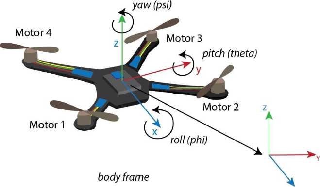
When the quadcopter flies in three-dimensional space, there are two coordinate systems, namely the body frame which means coordinates that move together with the quadcopter, and inertial frames which mean the reference point coordinates used for a quadcopter. The inertial frame or set point is fixed and immovable so that it can be a reference balance for the quadcopter (figure 5).
The mathematical model used is the rotational matrix used to change the movement of the quadcopter to match the inertial frame value (equation 2) [12].
Cb ∣i =
c(0)c(^)
(- c(φ) s(ψ) + s(φ) s(θ) c(ψy) (s(φ')s(φ) + c(φ)s(θ)c(φ))
c(θ)s(φ)
(c(φ}c(φ} + s(φ)s(θ)s(φ)) (-s(φ}c(φ} + c{φ)s{θ}s{φy)
-s(θ) s(Φ)c(θ) c(Φ)c(θ)
(2)
Cb ∣i means the conversion of the body frame value to the inertial frame value. φ (phi), θ (theta), ψ (psi) is a Euler Angle which is the rotation angle formed by a quadcopter when flying against the x, y, and z-axes.
x
inertial frame
Figure 5. Movement of quadcopter, body frame and inertial quadcopter frame
The tests in this research are: (1) Testing the motor, ESC, and propeller to get the motor and propeller coefficient to be used in the simulation. (2) Testing the quadcopter balance in the simulation, (3) to get the corresponding Kp, Ki, and Kd values. (4) Testing the implementation of the balance of the quadcopter on a real quadcopter with the PID values that have been obtained to get a maximum load that can be lifted. (5) Testing the balance of the quadcopter by giving a load in hovering.
The hardware implementation, as in figure 6 aims to obtain data that will be used to analyze the work of each hardware device.

Figure 6. Hardware Implementation in Quadcopter
We obtained quadcopter real data from the results of the implementation as in table 1.
Table 1. Quadcopter Hardware Specification
|
Motor |
ESC | ||
|
Mass (m) |
50 gr |
Mass (m) |
35 gram |
|
Distance to microcontroller(dm) |
22.225 cm |
Width (a) |
2.54 cm |
|
Height (h) |
3 cm |
Length (b) Distance to |
5.71 cm |
|
Radius (r) |
1.4 cm |
Microcontroller (ds) |
9.55 cm |
|
v motor Microcontroller + Middle Frame |
1000 rpm/v |
Arm | |
|
Mass (m) |
410 gr |
Mass (m) |
60 gram |
|
Radius (r) |
6 cm |
Height (r) |
1 cm |
|
Height (H) |
4.2 cm |
Length (L) Distance to |
19.7 cm |
|
Microcontroller (da) |
5.5 cm | ||
|
Propeller |
Battery | ||
|
Radius (A) |
0.127 m |
Mass (m) |
200 gram |
|
Pitch (p) |
0.114 m |
V Battery |
11.1 volts |
|
Total Mass |
990 gr | ||
3.2. Moment of Inertia Implementation
We assume Brushless Motor as a cylinder (figure 7), so we get the data in table 1. Moreover, to find the moment of inertia in the motor, equation 3 and 4 are used [13].

r
Figure 7. Brushless Motor
The moment of inertia on the motor against the x and y-axis :
Jx ,M= ,M =2 ^mr2 +3 mℎ 2]+2 ^mr2 +3 mℎ2+ mdm2j(3)
The moment of motor inertia against the z-axis:
Where m is the mass of brushless motor, r is the perpendicular distance, and d is diameter respectively.
-
3.2.2. ESC (Electronic speed controller)
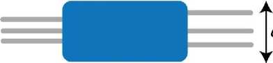
We assume ESC as a thin plate, so we get the data as in Table 2. Moreover, for the calculation of the moment of inertia using equation (5) and (6) [14].
◄-------->
b
Figure 8. ESC
The moment of ESC inertia to the x and y-axis :
Jx,ESC = JylESC = 2 [⅛mβ2] + 2 ∖mmb + + m⅛2] (5)
The moment of ESC inertia towards the z-axis is obtained by :
Jz,ESC = 4 [⅛m(d2 + b2) + mds]] (6)
Where b is the width and a is the height of ESC respectively.
-
3.2.3. Arm
The arm is assumed to be a cylinder, so the arm data is obtained as in Table 2. by using equation 7 calculation of the moment of inertia of the arm against the x and y-axis :
Jx,a = Jy,a = 2 [∣mr2 ] + 2 ^mr2 + ^mL2 + mdA2] (7)
Moreover, the calculation of the moment of arm inertia on the z-axis is obtained by using equation 8:
Jz,a = 4 [jmr2 + JmL2 + mdA2] (8)
Where L is a lift and A is an arm of the quadcopter respectively.
-
3.2.4. Middle Frame
All of the components in the center we assume as a cylinder, data for the middle frame are obtained in Table 2. The quadcopter rotation on the x and y-axes will calculate of the moment of inertia in the middle frame using the rotation equation in the middle of the diameter so that we can calculate the middle frame inertia Moment against the x-axis and y as in equation 9:
Jx ,h = Jy,H = [jmr2 +-JmH2 ] (9)
Moreover, quadcopter rotation on the z-axis, the moment of inertia formula with the middle frame calculate using equation 10 :
Jz ,H = [∣mr2] (10)
Where H is the middle frame of the quadcopter respectively.
By entering all parameter values, the moment of inertia is obtained for the entire quadcopter, as shown in Table 2.
Table 2. Moment of Inertia of Quadcopter
|
Jx |
Jy |
Jz |
Unit | |
|
Motor |
0.005009 |
0.005009 |
0.009899 |
Kg.m2 |
|
ESC |
0.000661 |
0.000661 |
0.001322 |
Kg.m2 |
|
Arm |
0.002413 |
0.002413 |
0.00362 |
Kg.m2 |
|
Middle Frame |
0.000429 |
0.000429 |
0.000738 |
Kg.m2 |
|
Total Moment of Inertia |
0.008513 |
0.008513 |
0.015579 |
Kg.m2 |
With configurations as in Table 2, the quadcopter can fly with a lift which can be calculated using equation 11 as follows [15]:
L= (11)
Where p is air density, V is speed, A is the area of the circle produced by the wing when rotated, ACl is the lift coefficient respectively.
With maximum V:
^max = 1000^voux 11.1 volt = 11100 rpm=185rev/sec
The rotational speed of propellers can be calculated as: v= . pitcℎ
v=185 rev ⁄secx 0.10922 meter = 20.3352 m/s
Then :
-
1 ∕ kg ∖
L = 1.225 (20.3352 m/s)2x (π x (0.11938 m)2)x0.1
-
2 ∖ ∕
L = 0.6125 —⅞ X 413.52 m/s2x 0.04475 m2 x 0.1
L = 1.1334 kgm/s2
Because it uses four motors then 4L =4x 1.1334 s2 = 4.5336 kg m/s2
Based on the results of the above calculations, the maximum lift can be obtained which can be produced by a quadcopter that has been designed at 4.5336 kg m/s2 . Then to be able to fly (hover). A half load is required from the maximum lift, so the quadcopter lift is 2.26 kg m/s2 .
Testing of loads that can be lifted by a quadcopter can be seen in Figure 9. The test aims to find the maximum load value that can be lifted by a quadcopter. Testing is also done by applying different throttles. Tests are carried out at three different fulcrums. This fulcrum is considered to represent the implementation of a quadcopter as a load carrier.

Figure 9. Testing the load at a different fulcrum. (a). In the middle, (b). Between motor 2 and 4, (c). Under motor 2
The first test is carried out at the fulcrum in the middle of the quadcopter. We place a digital hanging scale on the bottom of the quadcopter; then the scale is held on the floor, so it stays in the same position. The lift generated by a quadcopter will be represented as a mass by a hanging scale. When the quadcopter is pulled up, the mass value will increase in the quadcopter. The maximum load that can be lifted by quadcopter is 950g besides the load of the quadcopter itself. The second test, we place the load at 6 cm from the midpoint of the quadcopter or between motor 2 and 4. The maximum load that can be lifted by quadcopter is 580g. The third test is to find the maximum load that can be lifted by the load placed on one side of the quadcopter (under motor 2). The maximum load that can be lifted by quadcopter is 310g.
The overall test results can be seen in Table 3. It can be seen that giving different throttle value affects the load that can be lifted by the quadcopter; the higher the value of the throttle will produce a more significant lift.
Table 3. Test results for load values that can be lifted by quadcopter
|
Weight Point |
Throttle |
Volt input |
Lifted Mass |
|
80% |
12 v |
565 g | |
|
In the middle |
90% |
12 v |
800 g |
|
100% |
12 v |
950 g | |
|
80% |
12 v |
400 g | |
|
Between motor 2 and 4 |
90% |
12 v |
470 g |
|
100% |
12 v |
580 g | |
|
80% |
12 v |
220 g | |
|
Under motor 2 |
90% |
12 v |
270 g |
|
100% |
12 v |
310 g |
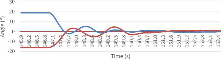
We analyze system behavior regarding response time specifications such as overshoot, settling time, peak time, rise time, and steady-state error on quadcopter during hovering. By using the value of Kp = 0.15 Ki = 0.1 and Kd = 0.004, we get the value of roll and pitch on the quadcopter.
Graphs of test results can be seen in figure 10.
Roll Pitch
(a). No-load Testing
Roll Pitch

(b). 500g load on motor 2 and 4 side
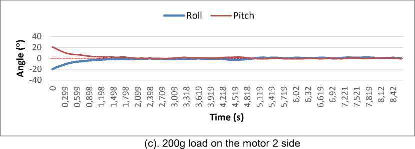
Figure 10. Roll and Pitch Graph Results
Based on the test chart data, it can be concluded that the response time of control on the quadcopter with the following table 4.
Table 4. Response Time Analysis
|
No |
Hover Testing |
Rise Time (Tr) s |
Settling Time (Ts) s |
Peak Time (Tp) s |
Overshoot (Os) % | ||||
|
Roll |
Pitch |
Roll |
Pitch |
Roll |
Pitch |
Roll |
Pitch | ||
|
1 |
No-load |
1.6 |
1.7 |
3 |
4.7 |
2.5 |
3.6 |
216 |
515 |
|
2 |
500g load on motor 2 and 4 side |
0.8 |
1.7 |
1.7 |
2.2 |
1.2 |
2.1 |
2336 |
270 |
|
3 |
200g load on the motor 2 |
1.29 |
1.49 |
5.19 |
4.8 |
4.4 |
4.6 |
182 |
123 |
side
While the table shows the value of RMS (Root mean square error), the error value of pitch and roll after settling time different from set-point. Tolerance time value required for settling time is 2% -5% of the final value. The results of the RMS Pitch and Roll for each test can be seen in Table 5. The data in the table shows the stability response in the quadcopter compared to the steady-state reference value or the value that can be tolerated from the given set-point.
Table 5. RMS Results
|
No |
Hover Testing |
Steady-state pitch |
RMS Pitch (o) |
steady state roll |
RMS Roll (o) |
|
1 |
No-load |
1.25 |
2,2 |
1.25 |
1,5 |
|
2 |
500g load on motor 2 and 4 side |
1.5 |
1,54 |
1.5 |
0,91 |
|
3 |
200g load on the motor 2 side |
1 |
0,9 |
1 |
1,1 |
It can be seen that the RMS value in test 1 without load slightly exceeds the steady-state reference since the quadcopter has no load to carry, then it moves more when interferences applied to test the stability. However, on tests 2 and 3 get the RMS value that corresponds to the steady-state reference value so that it can be concluded that the quadcopter can fly in a stable state.
Based on the research and testing that has been conducted, it can be concluded that Setpoint quadcopter for the steady or balanced position is 0.0008o, 0.9o for roll angle and pitch angle, respectively. There is a stability response in the Quadcopter even though we give a load on a different fulcrum; it can be seen from the RMS value obtained that it is by the steady-state tolerance of 2% -5% of the setpoint. Then, the Quadcopter can carry the maximum load with different fulcrums; if the load is placed at the fulcrum in the middle of the quadcopter, the maximum load is 950g. If the load is placed 6 cm from the middle of the quadcopter, it can carry the maximum load of 580 g. Moreover, if the load is placed on one motor, the maximum load is 310 g. In the development of the next system for future research, the quadcopter balance system will be improved upon landing with a load. Then, we try to display the simulation results visually.
References
-
[1] S. Sabikan and S. Nawawi, “Open-Source Project (OSPs) Platform for Outdoor
Quadcopter,” Journal Advance Research Design, vol. 24, no. 1, pp. 13–27, 2016.
-
[2] N. Ives, R. Pacheco, D. De Castro, R. Resende, P. Américo, and A. Magalhães,
“Stability Control of an Autonomous Quadcopter through PID Control Law," Int. Journal of Engineering Research and Application, vol. 5 no.5, p.07-10 2015.
-
[3] M. A. Lukmana and H. Nurhadi, “Preliminary study on Unmanned Aerial Vehicle (UAV)
Quadcopter using PID controller,” in 2015 International Conference on Advanced Mechatronics, Intelligent Manufacture, and Industrial Automation (ICAMIMIA), 2015, pp. 34–37.
-
[4] R. S. M. Sadigh, “Optimizing PID Controller Coefficients Using Fractional Order Based
on Intelligent Optimization Algorithms for Quadcopter,” in 2018 6th RSI International Conference on Robotics and Mechatronics (IcRoM), 2018, pp. 146–151.
-
[5] M. I. Fadholi, Suhartono, P. S. Sasongko, and Sutikno, “Autonomous Pole Balancing
Design In Quadcopter Using Behaviour-Based Intelligent Fuzzy Control,” in 2018 2nd International Conference on Informatics and Computational Sciences (ICICoS), 2018, pp. 1–6.
-
[6] A. Alkamachi and E. Erçelebi, “Modelling and Genetic Algorithm Based-PID Control of H-
Shaped Racing Quadcopter,” Arabian Journal for Science and Engineering, vol. 42, no. 7, pp. 2777–2786, Jul. 2017.
-
[7] A. S. Wibowo and E. Susanto, “Performance Improvement of Water Temperature
Control using Anti-windup Proportional Integral Derivative,” Lontar Komputer, vol. 9, no. 2, pp. 81-94, Aug. 2018.
-
[8] K. A. Tehrani and A. Mpanda, “PID Control Theory,” in Introduction to PID Controllers -
Theory, Tuning, and Application to Frontier Areas, 2015.
-
[9] E. Kuantama, T. Vesselenyi, S. Dzitac, and R. Tarca, “PID and Fuzzy-PID Control Model
for Quadcopter Attitude with Disturbance Parameter,” International Journal of Computers
Communications & Control, vol. 12, no. 4, pp. 519-532, Jun. 2017.
-
[10] D. K. Tiep and Y.-J. Ryoo, “An Autonomous Control of Fuzzy-PD Controller for Quadcopter,” International Journal of Fuzzy Logic and Intelligent Systems, vol. 17, no. 2, pp. 107–113, Jun. 2017.
-
[11] R. Aisuwarya, E. Asri, “Rancang Bangun Robot Tank Automatik Pendeteksi Halangan dengan Kendali Fuzzy Logic,” Jurnal Information Technology and Computer Engineering., vol. 2, no. 01, pp. 7–18, Mar. 2018.
-
[12] S. Wibawa, A. Sudana, and P. W. Buana, “Sistem Komunikasi Modul Sensor Jamak Berbasiskan Mikrokontroler Menggunakan Serial Rs-485 Mode Multi Processor Communication (Mpc),” Lontar Komputer, vol. 7, no. 2 pp. 122-131, Aug. 2016.
-
[13] H. L. Chan and K. T. Woo, “Design and Control of Small Quadcopter System with Motor Closed Loop Speed Control”, International Journal of Mechanical Engineering and Robotics Research, vol. 4, no. 4, pp.287-292, Aug. 2015.
-
[14] M. Z. Mustapa, “Altitude Controller Design for Quadcopter UAV,” Jurnal Teknologi, vol. 74, no. 1, Apr. 2015.
-
[15] D. Kotarski, Z. Benic, and M. Krznar, “Control Design for Unmanned Aerial Vehicles with Four Rotors,” Interdisciplinary Description of Complex Systems : INDECS, vol. 14, no. 2, pp. 236–245, Mar. 2016.
95
Discussion and feedback