The Simulation of Access Control List (ACLs) Network Security for Frame Relay Network at PT. KAI Palembang
on
LONTAR KOMPUTER VOL. 10, NO. 1 APRIL 2019
DOI : 10.24843/LKJITI.2019.v10.i01.p06
Accredited B by RISTEKDIKTI Decree No. 51/E/KPT/2017
p-ISSN 2088-1541
e-ISSN 2541-5832
The Simulation of Access Control List (ACLs) Network Security for Frame Relay Network at PT. KAI Palembang
Kurniatia1, Rahmat Novrianda Dasmena2
aTeknik Komputer, Universitas Bina Darma Jenderal A. Yani street number 03 Palembang, Indonesia 1kurniati@binadarma.ac.id
Abstract
PT. KAI Palembang is a branch of PT. Kereta Api Indonesia (KAI) Persero located in South Sumatra Province, where PT. KAI Persero is an Indonesian State-Owned Enterprise that organizes railway transportation which provide services including passenger and goods transportation. PT. KAI Palembang has a computer network connected to PT. KAI Persero central is located in Jakarta. Now, PT. KAI Palembang is trying to improve computer network security, where one of them is limiting the access of users who connected to PT. KAI Palembang computer network. This can be done by implementing Access Control Lists (ACLs) and Frame Relay on PT. KAI Palembang computer network. In this research used the Network Development Life Cycle (NDLC) method which has several stages, namely Analysis, Design, Simulation Prototyping, Implementation, Monitoring and Management. This research method is used because the results of this research will be displayed in the Cisco packet tracer simulator. In addition, the results of this research were tested using a ping test between computers to show that the ACLs design had been running well.
Keywords: Network, ACLs, NDLC, Cisco Packet Tracer, ping test
PT. KAI Palembang is an Indonesian state-owned enterprise located in South Sumatra Province, which provides rail transportation services for both passengers and goods. PT. KAI Palembang has a computer network that was connected to the PT. KAI Persero central computer network located in Jakarta, where the two networks were connected using a router device. A router is a device that will pass IP packets from a network to another network using the addressing and certain protocol method to pass that data packet [1]. IP packets contains IP Address which is a series of binary numbers between 32-bit to 128-bit which is used as the identification address for each host computer on the internet network [2]. Router have function to connect many small networks to a larger network and are called internetwork with TCP / IP technology-based to expand from LAN to WAN and MAN, router also used to connect networks that use different media [3]. Routing needs to be done to the router device so that it can be used, where routing is the process of directing data packets to get the destination from one location to another [4]. To do the routing process, a routing protocol is needed, where the routing protocol is the protocol used in dynamic routing and allows routers to share information about networks and connections between routers [5]. In this research, Enhanced Interior Gateway Routing Protocol (EIGRP) is used, which is a cisco routing protocol that works on cisco routers and on internal route processors that found on layer core switches and cisco distribution layer switches and EIGRP is also a classes and enhaced distance vector protocol [6]. In addition, also need a switch device which have function as a link between the computer network of rooms were located in PT. KAI Palembang. A switch commonly called a smart hub was used to connect between one computer and another computer in a LAN [7].
The problem that occurs in this research is the lower levels of network security, so it is necessary to make efforts for improve computer network security by limiting user access to communication between networks on the PT. KAI Palembang computer network. Therefore in this research, do the application of Access Control List (ACLs) and Frame Relay on the PT. KAI Palembang computer network. ACLs are a list of licensing or rejection statements that are applied to network addresses or the uppermost protocol layer and ACLs also used to select packets that go in and out of the network [8] while Frame relay is a technology that relies on frame- frame that is forwarded to send data [9], where Frame is a packet data [10]. In order to implement both of these technologies, so necessary to build a Virtual Local Area Network (VLAN) by utilizing router and switch, where VLAN are logical groupings of users and network resources that are connected to determined ports on a switch administratively [11]. VLAN is an option because it regulate networks based on their classification techniques, namely through MAC addressing, ports and so on that make flexible VLAN networks [12]. The entire research was carried out using a Cisco packet tracer simulator, where cisco packet tracer is a simulator of network tools issued by cisco that often used as a medium of learning and training and also often used in computer network simulation research fields [13]. The main purpose of the cisco packet tracer is to provide tools for participants and instructors to be able to understand the principles of computer networking and also build skills in the network configuration field that use cisco [13].
The research method used in the current research is the Action Research method wherein this method is described, interpreted and explained a condition at the same time in order to make changes or interventions with the aim of improvement and participation [14]. The following in Figure 1 are the stages of the action research method used:

Diagnosing
Learning
Evaluating
Action Planning
METODE
ACTION RESEARCH
Kelola : Rahmat Novriatida D
Action
Taking
Figure 1. Action Research Method [15]
In Figure 2. below is the result of a topology design that researcher have designed on PT. KAI Palembang computer network, where the researcher added 2 routers and implemented a star-
bus topology with the aim that there were alternative paths could be used if the main line was cut off. The following picture below is the Network Topology that designed using the Cisco packet tracer simulator.
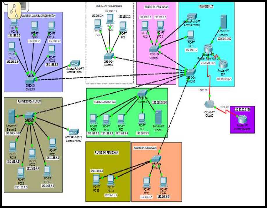
Figure 2. Network Topology Design in PT. KAI Palembang.
Virtual Local Area Network (VLAN) is a network that connect the same network although different locations with configuration in switch device using the trunking method, the switch is connected with a router to connect a predetermined VLAN network [16]. VLAN mapping is done to ease the Frame Relay configuration and VLAN also divide the device into several rooms based on their functions. The following table below is the VLAN mapping that used in this research:
Table 1. VLAN mapping
|
No. |
Rooms |
VLAN |
|
1 |
IT and Service Room |
10 |
|
2 |
Safety Room |
20 |
|
3 |
Financial and Billing Room |
30 |
|
4 |
Documentation Room |
40 |
|
5 |
Rail and Bridges Room |
50 |
|
6 |
HR and General Room |
60 |
To be able to communicate on a private network or on the internet public network every host on the computer network must be identified by an IP address
Table 2. IP Address Scheme
|
No. |
Rooms |
Network address |
IP address |
Subnet mask |
Default gateway |
|
1 |
IT and Service Room |
192.168.1.0/28 |
192.168.1.2 s/d 192.168.1.3 |
255.255.255.0 |
192.168.1.1 |
|
2 |
Safety Room |
192.168.2.0/28 |
192.168.2.2 s/d 192.168.2.3 |
255.255.255.0 |
192.168.2.1 |
|
3 |
Financial and Billing Room |
192.168.6.0/28 |
192.168.6.2 s/d 192.168.6.4 |
255.255.255.0 |
192.168.6.1 |
|
4 |
Documentation Room |
192.168.5.0/28 |
192.168.5.2 s/d 192.168.5.4 |
255.255.255.0 |
192.168.5.1 |
|
5 |
Rail and Bridges Room |
192.168.3.0/28 |
192.168.3.2 s/d 192.168.3.5 |
255.255.255.0 |
192.168.3.1 |
|
6 |
HR and General Room |
192.168.4.0/28 |
192.168.4.2 s/d 192.168.4.5 |
255.255.255.0 |
192.168.4.1 |
The following table below is the access control list (ACLs) design that will be applied in this research:
Table 3. ACLs Design
|
No. |
Rooms |
Cannot access |
|
1 |
HR and General Room |
IT Server |
|
2 |
All rooms except the IT room |
Internet (ISP) |
|
3 |
Financial Room |
IT Server |
The researcher designed frame relay from PT. KAI Palembang headed to PT. KAI Central in Jakarta. The researcher added a cloud as a media to connect of two networks with a WAN shell, where the design is as follows
Table 4. Frame Relay Design
|
No. |
Router |
IP Address |
DLCI |
|
1 |
Palembang |
10.1.1.1/24 |
100 |
|
2 |
Jakarta |
10.1.1.2/24 |
200 |
To give the identity of a VLAN or VLAN identity number is called a VLAN ID. Used to mark related VLAN, by configuring it as follows:
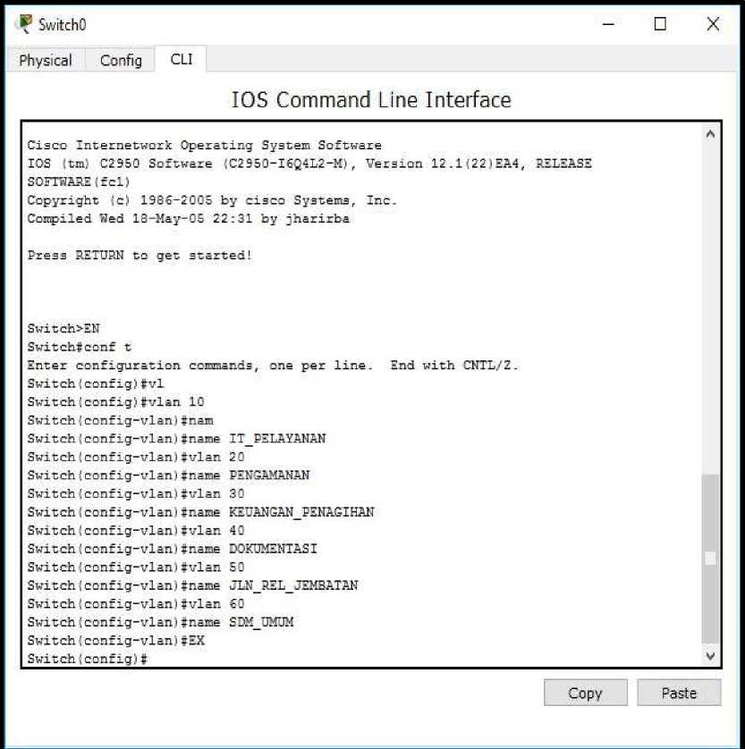
Figure 3. VLAN Configure on a switch
-
1) Configure the access link interface to the PC
The interface configuration to the PC aim to access the VLAN ID that was created on the switch. Then to connect the interface using an access link command used to connect a computer with switch access links is a configured switch port.
Switch (config) #int fa0 / 2
Switch (config-if) #switchport access vlan 10
Switch (config-if) #switchport mode access
Switch (config) #int fa0 / 3
Switch (config-if) #switchport access vlan 20
Switch (config-if) #switchport mode access
Switch (config) #int fa0 / 4
Switch (config-if) #switchport access vlan 30
Switch (config-if) #switchport mode access
Switch (config-if) #int fa0 / 5
Switch (config-if) #switchport access vlan 40
Switch (config-if) #switchport mode access
Switch (config-if) #int fa0 / 6
Switch (config-if) #switchport access vlan 50
Switch (config-if) #switchport mode access
Switch (config-if) #int fa0/7
Switch (config-if) #switchport access vlan 60
Switch (config-if) #switchport mode access
Switch (config-if) #ex
2) Setting interconnection between VLAN
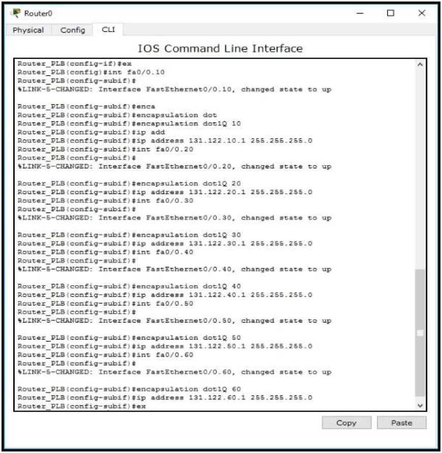
Figure 4. Setting interconnection between VLAN
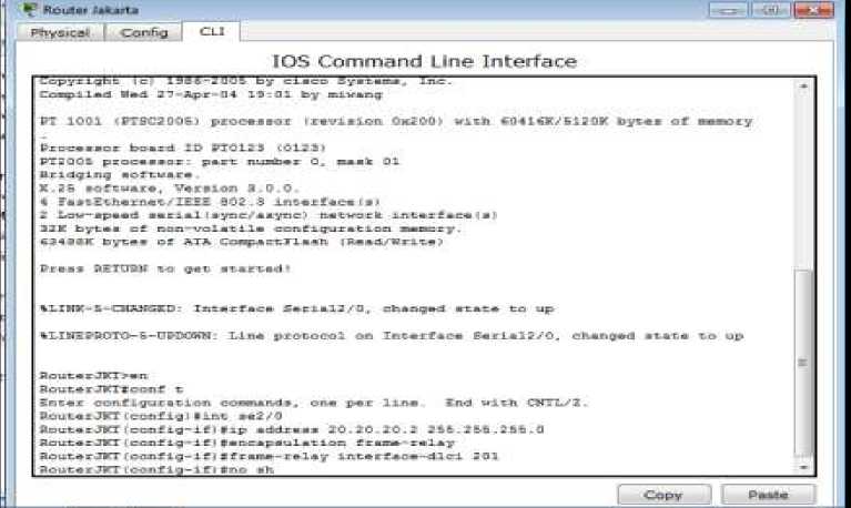
Frame Relay have function for communication between branches of the company, for example the branch office PT. KAI Palembang wants to communicate with the PT. KAI central in Jakarta and the communication process become more simple.
-
1) Palembang Router Configuration
ψ RσUtw Palembeng c * S’
Physical ⊂ont-⅛ CLl ∣
IOS Command Line Interface
RouterFLB>eπ SOTrcerPLBfrTOTiC C-Snter conf ιgur *tιcn ccsnanda, tana per line Cnd with CWΠ√2. AoutectLB.cβnfLgI■Iat eel/ O
AoutecrLBscenfig-IfMLp addc∙∙∙ 20.20.2(1.1 2BB. Σ≡≡ . 2 BE .0 RoucexFLB < conf Ig-If J iencapsulecLon fr*M-x∙Xa/ OouterPLB(σonftg-if JITr∙s∙∙-relay InverfBc-Olci IOl

BouterPLB-IceflfLg-IfMfraBMi-ZeLey Lnvezface-dlei IOL
BouxerPLBrIcofifLg-IfMno Bh
Route cFLB < conf Lg^ ι £ ,ι t
ILiniPSOrO-B-UFDOWK Lxce pxot∞l an Xatexface SexLaiazO1 PAangnd etale tn dove
⅝LIXtFS0Γ0-6-CPDCWK- LUx protocol on Interface Serlal3∕0r Changed state to up
RoutarFLB -I OOflflga it.'t SRC Zely O
RouiarPLB-Iconfxg-ItMxp Mddxaae 100.LC-1.1 IBS .XSi .2Bi .O
RautaxPLB -I conf Lg-Xf) Ino an
BouterPLB-IcoflfLg-IfMint se2∕0
BouterPLBtcoflfLg-IfMLp address 10.10 10.1 2K.2SS.2iB.0
RoueerFLBtcanrig-IfJ r
00:01:03: WOJSFr-B-AiXJCHS: Froceoe 1, Knr IOO . 1OO - IOO . 2 an SerialJyO Erne TtlLL xc
DOWXr KieXgAbcr Dcvn- Interface deem ox Satacbed
RoucezFLB-Ic-MLfLg-LfMno Bit
RouterFLB < confl^^Mj^^^
Cupv PdMe
Figure 5. Palembang Router Configuration
-
2) Jakarta Router Configuration

-
3) Cloud configuration
Cloud is a combination of the computer technology used (computing) in a network with internetbased development (cloud) that has a function to run programs or applications through connected computers at the same time, but not all are connected through the internet using cloud computing. This cloud-based computer is a technology that makes the internet the central server for managing data and user applications. This technology allows users to run programs without installation and allows users to access their personal data through computers with internet access. As well as the benefits of cloud in everyday life can store all data on the server centrally, data security, high flexibility and scalability and long-term investment.
-
a) Port to the Palembang Router
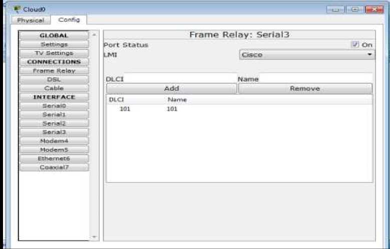
Figure 7. Port to the Palembang Router b) Port to Jakarta Router
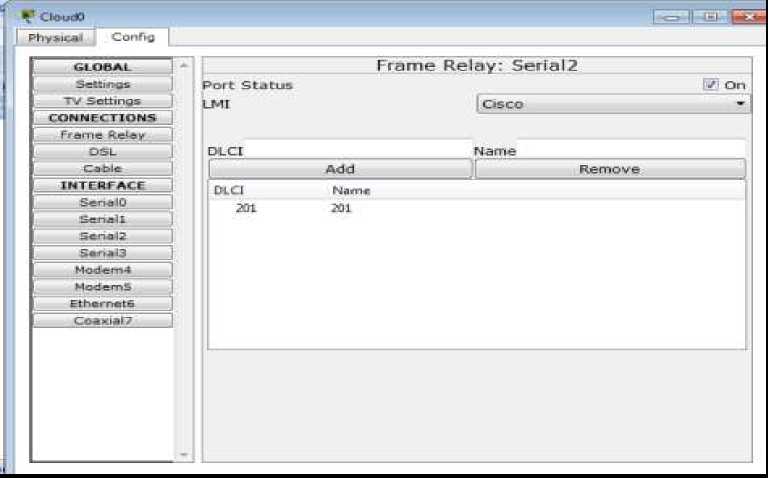
Figure 8. Port To the Jakarta Router
c) Connect frame relay from Palembang to Jakarta
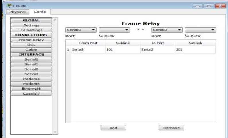
Figure 9. Frame Relay From Palembang to Jakarta
Each router that is in one domain has a identical database to each other, so that large network can be broken down into smaller areas and react very quickly to changes that occur on the network. Here is the configuration:
RouterPLB (config) #router eigrp 10
RouterPLB (config-router) #no auto-summary
RouterPLB (config-router) #network 192.168.1.0 0.0.0.255
RouterPLB (config-router) #network 192.168.2.0 0.0.0.255
RouterPLB (config-router) #network 192.168.3.0 0.0.0.255
RouterPLB (config-router) #network 192.168.4.0 0.0.0.255
RouterPLB (config-router) #network 192.168.5.0 0.0.0.255
RouterPLB (config-router) #network 192.168.6.0 0.0.0.255
RouterPLB (config-router) #network 100.10.1.0 0.0.0.255
RouterPLB (config-router) #network 10.10.10.0 0.0.0.255
RouterPLB (config-router) #network 20.20.20.0 0.0.0.255
RouterPLB (config-router) #end
RouterPLB # wr
-
1. Configure the EIGRP Router on the JKT Router
RouterJKT (config) #router eigrp 10
RouterJKT (config-router) #no auto-summary
RouterJKT (config-router) #network 20.20.20.0 0.0.0.255
RouterJKT (config-router) #end
-
2. Configuring the EIGRP Router on the ISP Router
RouterISP (config) #router eigrp 10
RouterISP (config-router) #no auto-summary
RouterISP (config-router) #network 10.10.10.0 0.0.0.255
RouterISP (config-router) #end
This testing phase is intended to find out whether the Access Control List (ACLs) configuration has been running properly according to the ACLs design table that has been presented previously. Following are some examples of ping test from several computer clients on the PT. KAI Palembang computer network:
To be able to test the connection from HR and general room to the Lampung Router, the researcher ping the HR and general room client to the Lampung Router IP address : 101.11.10.2. The following results can be seen in the picture below.
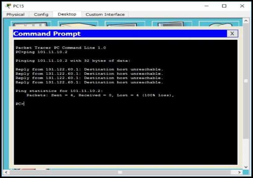
Figure 10. Ping test on HR and General Room to Lampung Router
To be able to test the connection from the IT room to the ISP, the researcher ping the IT Room client to the ISP IP address : 10.20.30.2. The following results can be seen in the picture below.
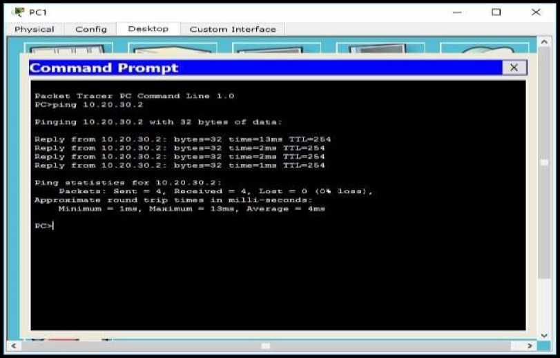
Figure 11. Ping test IT Room to an ISP Router (Internet)
To be able to test the connection from the Financial room to the Lampung Router, the researcher ping the Financial room client to the Lampung Router IP address : 101.11.10.2. The following results can be seen in the picture below.
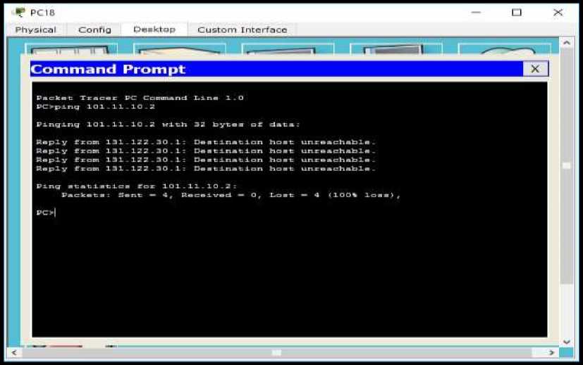
Figure 12. Ping test Financial Room to the Lampung Router
To be able test the connection from Documentation Room to the ISP, the researcher ping the Documentation room client to the ISP IP address : 10.20.30.2. The following results can be seen in the picture below.
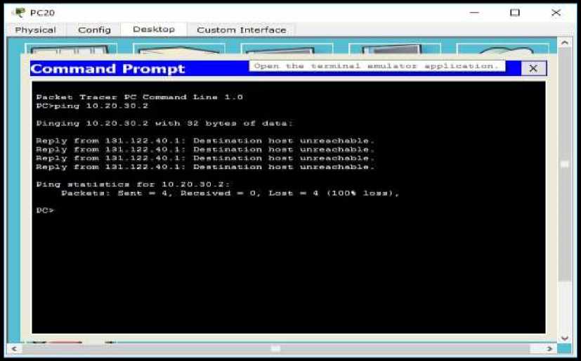
Figure 13. Ping test Documentation Room to the ISP Router (Internet)
3.13. Ping test from IT Room to the Billing Room
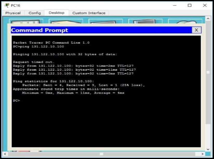
Figure 14. Ping test IT Room to the Billing Room
From the results of connection testing between several clients on the PT. KAI Palembang computer network that has been obtained above, it can be seen that the Access Control List (ACLs) configuration has run according to the ACLs design table (Table 3). Can be seen in table 5 below:
Table 5. Connection testing results
|
No. |
Testing Result |
|
1 |
Ping test on HR and General Room not connected to Lampung Router |
|
2 |
Ping test IT Room to an ISP Router connected (Internet) |
|
3 |
Ping test Financial Room to the not connected Lampung Router |
|
4 |
Ping test Documentation Room to not connected the ISP Router (Internet) |
|
5 |
Ping test IT Room to the Billing connected Room |
This research use the Network Development Life Cycle (NDLC) method, where the NDLC method stages that have been carried out in this research are Analysis, Design and Simulation Prototyping so that the next stages such as Implementation, Monitoring and Management can be carried out by next researchers. From the final results of this research which the connection testing between several clients on PT. KAI Palembang computer network show that the
application of Access Control Lists (ACLs) can limit a user's access to communication, where only users who are registered in the users list database are permitted through ACLs configuration that can connected and communicated. That way, the results of this research can be used as a solution for the network security problems faced by PT. KAI Palembang.
References
-
[1] A. N. Asyikin, N. Saputera, and E. Yohanes, “Sistem Manajemen Hotspot di Politeknik
Negeri Banjarmasin menggunakan Mikrotik Router OS,” Jurnal Poros Teknik, vol. 5, no. 1, pp. 31–35, 2013.
-
[2] N. Yulianto and F. Bacharuddin, “Perancangan Sistem Informasi Parkir dengan WiFi
berbasis Arduino,” Lontar Komputer: Jurnal Ilmiah Teknologi Informasi, vol. 7, no. 3, pp. 132–137, 2016.
-
[3] H. A. Musril, “Analisis Unjuk Kerja RIPv2 dan EIGRP dalam Dynamic Routing Protocol,”
Jurnal Elektro Telekomunikasi Terapan (JETT), vol. 2, no. 2, 2015.
-
[4] S. Alimi, Sukiswo, and I. Santoso, “Kinerja Routing Fisheye State Routing (FSR) pada
Jaringan WPAN 802.15.4 (Zigbee) Topologi Mesh,” TRANSIENT, vol. 2, no. 1, pp. 87– 96, 2013.
-
[5] F. U. Hasanah and N. Mubarakah, “Analisis Kinerja Routing Dinamis dengan Teknik RIP
(Routing Information Protocol) pada Topologi Ring dalam Jaringan LAN (Local Area Network) menggunakan Cisco Packet Tracer,” SINGUDA ENSIKOM, vol. 7, no. 3, pp. 118–124, 2014.
-
[6] D. Yolanda, S. H. Pramono, and M. F. E. Purnomo, “Simulasi Kinerja Routing Protokol
Open Shortest Path First (OSPF) dan Enhanced Interior Gateway Routing Protocol (EIGRP) menggunakan Simulator Jaringan OPNET Modeler v. 14.5,” Jurnal Mahasiswa TEUB, vol. 1, no. 2, pp. 1–6, 2013.
-
[7] J. Enterprise, Trik Membuat Jaringan Komputer dan Wifi, 1st ed. Jakarta: PT. Elex
Media Komputindo, 2014.
-
[8] P. Simanjuntak, C. E. Suharyanto, and Jamilah, “Analisis Penggunaan Access Control
List (ACL) dalam Jaringan Komputer di Kawasan Batamindo Industrial Park Batam,” Journal Information System Development (ISD), vol. 2, no. 2, 2017.
-
[9] R. N. Dasmen, “Simulasi Teknologi Frame Relay pada Jaringan VPN Menggunakan
Cisco Packet Tracer,” Jurnal Digital, vol. 1, no. 1, pp. 45–55, 2018.
-
[10] H. Supendar and Y. Handrianto, “Teknik Frame Relay dalam Membangun Wide Area
Network dengan Metode Network Development Life Cycle,” Bina Insani ICT Journal, vol. 4, no. 2, pp. 121–130, 2017.
-
[11] H. Yani, P. A. Jusia, and H. Rohayani. AH, “Analisis dan Perancangan Sistem Manajemen Network berbasis Virtual Local Area Network (Studi Kasus: PT. Sumbertama Nusa Pertiwi),” in Seminar Nasional Teknologi Informasi dan Multimedia 2013, 2013.
-
[12] R. Tulloh, “Analisis Performansi VLAN pada Jaringan Software Defined Network (SDN),” Jurnal INFOTEL (Informatika - Telekomunikasi - Elektronika), vol. 9, no. 4, pp. 406–411, 2017.
-
[13] Zulkipli, M. Efendi, and Sihkabuden, “Pengembangan Modul Sistem Keamanan Jaringan berbasis Simulasi Cisco,” Jurnal Pendidikan: Teori Penelitian dan Pengembangan, vol. 1, no. 3, pp. 399–408, 2016.
-
[14] R. N. Dasmen, “Implementasi Metode VLSM (Variable Length Subnet Mask) pada Pemetaan IP Address LAN (Local Area Network) STIPER Sriwigama Palembang,” Computatio: Journal of Computer Science Information Systems, vol. 2, no. 2, pp. 112– 118, 2018.
-
[15] R. N. Dasmen, “Implementasi Raspberry Pi 3 sebagai Wireless Access Point pada STIPER Sriwigama Palembang,” Jurnal Informatika: Jurnal Pengembangan IT, vol. 3, no. 3, pp. 387–393, 2018.
-
[16] O. K. Sulaiman, “Simulasi Perancangan Sistem Jaringan Inter VLAN Routing di Universitas Negeri Medan,” CESS (Journal of Computer Engineering, System and Scence), vol. 2, no. 1, pp. 17–21, 2017.
61
Discussion and feedback