The Analysis of the Effect and Reduction of Carrier Frequency Offset in Orthogonal Frequency Division Multiplexing (OFDM) Multiple Input Multiple Output (MIMO)
on
Majalah Ilmiah Teknologi Elektro, Vol. 19, No. 2, Juli - Desember 2020
DOI: https://doi.org/10.24843/MITE.2020.v19i02.P14 219
Analysis of the Effect and Reduction of Carrier Frequency Offset in Orthogonal Frequency Division Multiplexing
(OFDM) Multiple Input Multiple Output (MIMO)
Willy Sucipto1 , I Nyoman Pramaita2 , NMAE Dewi Wirastuti3
[Submission: 09-09-2020, Accepted: 13-12-2020]
Abstract— The development of cellular telecommunication provides users to experience fast and stable transmission. This standard of transmission is proportional to the needs of the devices and systems used. We are currently in the fourth generation (4G) of cellular technology. The key technologies used in 4G are Orthogonal Frequency Division Multiplexing (OFDM) which uses the concept of orthogonality for bandwidth efficiency and Multiple Input Multiple Output (MIMO) which uses the concept of diversity to improve performance. But in implementation this system will have problems with the transmission channel. The problem that occurs is signal attenuation due to Carrier Frequency Offset (CFO). This CFO will cause the orthogonal character built from the OFDM system to experience a decline in performance. The decline in performance is due to the occurrence of Intercarrier Interference (ICI). To overcome this problem, the method used in this simulation are Improved Sinc Power Pulse (ISP) and Rectangular Pulse (REC). The results showed that ISP had a relatively better BER value than REC and without using the pulse shaping method. The minimum BER value obtained from the simulation is ISP with a value of 0.0001 while REC produces a value of 0.0006 and without pulse shaping produces a BER value of 0.0038.
Intisari— Perkembangan telekomunikasi seluler memberikan pengguna untuk merasakan transmisi yang cepat dan stabil. Transmisi yang cepat dan stabil ini sebanding dengan kebutuhan perangkat dan sistem yang digunakan. Kita saat ini berada pada generasi ke-empat (4G) teknologi seluler. Teknologi kunci yang digunakan pada 4G adalah Orthogonal Frequency Division Multiplexing (OFDM) yang menggunakan konsep ortogonalitas untuk efisiensi bandwith dan Multiple Input Multiple Output (MIMO) yang menggunakan konsep diversity untuk meningkatkan unjuk kerja. Tetapi dalam Implementasinya sistem ini akan mempunyai masalah pada kanal transmisi. Masalah yang terjadi adalah pelemahan sinyal karena Carrier Frequency Offset (CFO). CFO ini akan menyebabkan karakter ortogonal yang dibangun pada sistem OFDM mengalami penurunan unjuk kerja. Penurunan unjuk kerja ini dikarenakan terjadinya Intercarrier Interference (ICI). Untuk mengatasi hal tersebut maka diperlukan suatu metode untuk memperbaiki unjuk kerja sistem. Metode yang dipakai dalam simulasi ini adalah Improved Sinc Power Pulse dan Rectangular Pulse (REC).
Hasil penelitian menunjukan ISP memiliki nilai BER yang relatif lebih baik dibanding dengan REC dan tanpa menggunakan metode pulse shaping. Nilai Minimum BER yang didapat dari simulasi adalah ISP dengan nilai 0,0001 sedangkan REC menghasilkan nilai 0,0006 dan tanpa pulse shaping menghasilkan nilai BER 0,0038.
Kata Kunci— Pulse Shaping, Improved Sinc Power Pulse, Rectangular Pulse, OFDM, MIMO, ICI, CFO.
Cellular telecommunication is growing rapidly over time. This development aims to meet the needs of users in terms of service quality and system performance. Every decade, the wireless industry release the standard for mobile communications is capable of transmitting data faster than previous communication standards. The faster transmission is proportional to the technological advances used in the transmission system.
We are currently in the fourth generation (4G) of the mobile telecommunications standard. The multiplexing technique used in 4G is Orthogonal Frequency Division Multiplexing (OFDM) [1]. With OFDM, the transmission technique uses multiple frequencies (Multi-carrier) which are mutually orthogonal so that bandwidth efficiency can occur. The key technology used in 4G is Multiple Input Multiple Output (MIMO) [2]. MIMO is used to obtain better spectral efficiency because of the limited bandwidth. MIMO uses a larger number of antennas so that it functions to multiply the transmitted signal and make the reflected signal as the main signal amplifier. Bandwidth usage on the receiver and transmitter side with the Almouti Space Time Block Code (STBC) scheme as a detector to be combined with the MIMO system. In short, OFDM MIMO can increase spectrum efficiency and improve channel quality with multiple antennas at the transmitter and receiver.
The main disadvantage of OFDM MIMO is susceptible to carrier frequency offset between transmitter and receiver. The effect of this Carrier Frequency Offset (CFO) is that the orthogonal character of the subcarrier can be lost and it can experience a frequency shift or so-called Intercarrier Interference (ICI) [3]. This CFO is caused by the doppler effect and due to the mismatch of frequencies on the transmitting and receiving oscillators. ICI will reduce the performance of the system. Therefore, efforts are needed to reduce ICI in the OFDM system. In previous research about this problem, author just explain about Improved Sinc Power Pulse (ISP), without combine with MIMO which is the key Technology in 4G [4]. In this research, the author use Sinc-p-ISSN:1693 – 2951; e-ISSN: 2503-2372

Power Pulse (ISP) and Rectangular Pulse (REC) method to overcome the main causes of ICI events in the system and use MIMO to upgrade the systems performance.
-
A. MIMO-STBC (Multiple Input and Multiple Output – Space Time Block Coding)
In radio waves, MIMO is a method of multiplying capacity by using multiple antennas to transmit and receive data. MIMO uses multiple transmitter and receiver antennas to improve system performance. MIMO is a technology that uses multiple antennas to coherently decompose more information than using a single antenna. Two important advantages given to 802.11n are antenna diversity and spatial multiplexing. MIMO technology relies on signals from multiple directions. These signals from various directions are reflected signals that arrive at the receiving antenna shortly after the transmission of the main one line signal arrives (Line of sight) [5].
-
B. OFDM (Ortoghonal Frequency Division Multiplexing)
OFDM is a transmission technique that uses multiple carrier frequencies (multicarrier). Each sub-carrier is made orthogonal and harmonic to one another, so that the adjacent sub-carriers can be overlapped without causing ICI. OFDM spectrum efficiency is higher when compared to conventional modulation techniques like Frequency Division Multiplexing (FDM) [6]. The Figure 1 below shows the difference between OFDM and FDM.
Frequency
Savings bandwith
(b)
Figure 1. (a) FDM and (b) OFDM
Frequency
-
C. Pulse Shaping
In this MIMO OFDM spectrum, each subcarrier consists of a main lobe and many side lobes. When the orthogonality between the subcarriers is reduced, the side lobe will have the potential to generate ICI power in the middle area of each subcarrier. ICI power will increase when the carrier frequency offset also increases. The purpose of this pulse shaping method is to eliminate or minimize the side lobe amplitude of a subcarrier that has the potential to cause ICI so that the ICI will experience reduction and also be able to improve the performance of the MIMO OFDM system [7].
In this thesis, the types of pulse shaping Improved Sinc-power Pulse (ISP) and Rectangular Pulse are used which are able to reduce the ICI power from the side lobe. The equation of REC is as follows [8]:
Prec(Lf) = Sinc(LfT) (1)
While the ISP equation is as follows:
Pisp(Lf) = C-a^r? Sinc11(LfT) (2)
where ∆f represents the change in frequency due to the CFO between the sending and receiving oscillators and ∆fT represents the normalized frequency offset value. The parameter a is used to vary the amplitude of the pulse and n represents the degree of the sinc function [9].
-
D. Carrier Frequency Offset
Carrier Frequency Offset (CFO) or frequency offset is caused due to the Doppler effect or due to a frequency mismatch in the transmitting and receiving oscillators which results in loss of orthogonality [10]. The loss of orthogonality between these subcarriers will cause ICI to occur because the side lobe of a subcarrier will interfere with other subcarriers. CFO has a normalized value which is symbolized by ε [11] [12]. The value of ε will show how much the subcarrier shift is detected by the receiving oscillator [13]. where the values of ε ≤ 1 and ε have an equation as shown in Equation (3) below [14].
ε= [offset Lfe
(3)
where the normalized value of CFO is the amount of frequency that occurs due to the movement of the transmitting antenna (doppler shift), foffset is the amount of frequency offset due to frequency mismatches on the sending and receiving oscillators and Δfc is the sub-carrier spacing, which is a parameter to determine the loss that occurs due to frequency shift.
-
A. Data Collection Method
In this study, the data used are generated from simulation. The step of simulation is to make a MIMO-STBC simulink model on the selective fading channel with the impact of frequency offset. The simulation model includes random bit generation, BPSK modulation, OFDM process and running the MIMO-STBC process through the AWGN channel and selective fading and calculating BER and Eb/No values as system performance parameters.
The parameter that used in this simulation are shown on the Table I below:
TABLE I
Simulation Parameters
|
Parameter |
Value |
|
Number of Bit |
1.000.000 |
|
Type of channel |
Frequency Selective Fading |
|
length cyclic prefix |
16 (0.25x64) |
|
Frequency offset |
3 kHz, 6 kHz, and 9 kHz |
|
Normalized FO (ε) |
0,2 0,4 and 0,6 |
|
Subcarrier spacing |
15 kHz |
B. Research Flow
This research has a process flow to carry out the stages of research. The Flow of research and simulation are shown in Figure 2 below.
DOI: https://doi.org/10.24843/MITE.2020.v19i02.P14
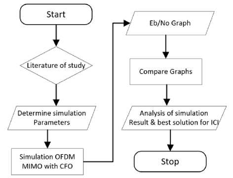
Figure 2. Research Flow
The simulation is done by changing the frequency offset parameter. From these changes will be analyzed the effect of CFO on system performance. After seeing the effect of the CFO, the pulse shaping reduction technique will be applied. In this study, two types of reduction techniques were used, namely Rectangular Pulse Shaping (REC) and Improved Sinc Pulse Shaping (ISP).
frequency offset and without it. In this simulation, the BER value compared to Eb/No from each system simulation. The frequency offset values used in this simulation vary, as follows: 3 kHz, 6 kHz, and 9 kHz.
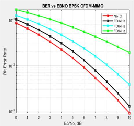
Figure 3. Comparative Performance with CFO
C. Simulation Process and Procedure
First, determine the parameters according to literature and according to the simulation target to be achieved. In this research author want to discover effect of CFO in 4G systems, discover the problems and make solutions to the problems. To discover this effect of CFO, author use particular parameter in the simulation to compare channel without CFO and channel with CFO. The CFO used varies to discover the effect of the CFO. This effect is indicated by the BER value. the worse the BER, the worse the influence of the CFO.
After author discover the problem cause by CFO with BER value, the next step is to make solution about CFO in MIMO OFDM. In this research author use ISP and REC methods. Author use system with CFO and without pulse shaping for the first simulation. it is used to see the comparison without CFO and with the effect of CFO.
For the final simulation author compare the system without CFO with pulse shaping effect to the systems. Effect of ISP and REC are shown by comparison BER to Eb/No. The smaller the ber value, the better the system performance.
-
A. Comparative Analysis of OFDM MIMO System Performance With and Without Frequency Offset
CFO has a bad impact in OFDM signals because it makes the orthogonal character of the signal change, so that it makes signal attenuation to occur. Figure 3 shows a comparison of the performance of OFDM MIMO with the effect of
Figure 4 shows the comparison of the effect of frequency offset on the OFDM MIMO system. The red line shows the OFDM MIMO system without the effect of frequency offset. The black line shows the effect of the frequency offset with a value of 3 kHz, the blue line shows the effect of the frequency offset with a value of 6 kHz, while the green line shows the effect of the frequency offset with a value of 9 kHz.
By looking at the BER vs Eb/No on Figure 3, it can be seen that the greater the frequency offset value used, the greater the BER value in the OFDM MIMO system. Based on this, it can be seen that the performance of OFDM MIMO system without frequency offset is better than the effect of frequency offset, where the greater the frequency offset simulated, the higher the BER. This is because frequency offset causes a loss of signal orthogonality by shifting the side lobe subcarrier. This side lobe subcarrier shift causes inter carrier interference (ICI) which can interfere with the performance of the OFDM MIMO system.
-
B. Comparative Analysis of OFDM MIMO System
Performance With and Without Pulse Shaping
The block diagram of the OFDM MIMO system combined with the pulse shaping method can be seen in Figure 4. Pulse shaping forms the pulse of the symbols transmitted. Each symbol that is sent will be multiplied by the pulse shaping function so that the side lobe has been compressed and results in reduction of the ICI.
Willy Sucipto: Analisis of the Effect …
p-ISSN:1693 – 2951; e-ISSN: 2503-2372

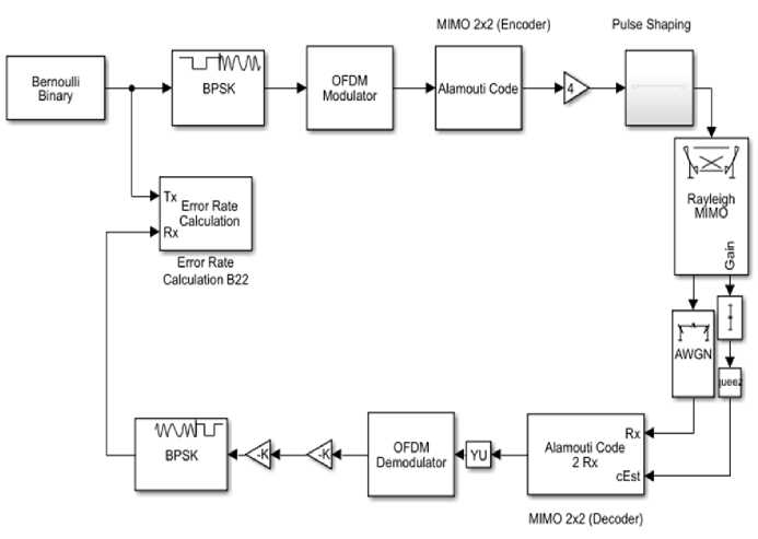
Figure 4. Diagram Block of OFDM MIMO System with Pulse Shaping
By performing simulations based on block diagram modeling as shown in Figure 4, the results are obtained in the form of a comparison graph using pulse shaping as shown in Figure 5. The 6 kHz frequency offset is used as the sample in this simulation. The black line shows the effect of frequency offset on the OFDM MIMO system without pulse shaping. The yellow line shows the effect of the 6 kHz frequency offset by applying the rectangular pulse to the OFDM MIMO system. The magenta colored line shows the effect of a frequency offset of 6 kHz with the implementation of an Improved sinc power pulse in the OFDM MIMO system.
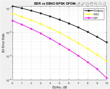
Figure 5. Comparative Performance with Pulse Shaping
Based on the graph in Figure 5, it can be seen that the type of pulse shaping Improved Sinc Power Pulse (ISP) has the ability to reduce ICI which is better than the Rectangular Pulse. This is because the Improved Sinc Power Pulse (ISP) is
able to form the side lobe of each subcarrier as if it looks flat where when there is a frequency offset there will be no shift in the side lobe of the subcarrier so that the subcarrier does not lose its orthogonality to prevent ICI.
By analyzing the simulations that have been run regarding the application of pulse shaping in OFDM MIMO systems that are affected by frequency offset, it can be concluded that the application of pulse shaping has a good impact on the performance of the OFDM MIMO system. That is because the interference effect from the subcarrier can be minimized by reducing the ICI power. From the simulation it can also be concluded that the Improved Sinc Power Pulse (ISP) is able to reduce ICI better than the Rectangular Power Pulse (REC).
In this simulation, it can be seen that MIMO OFDM in the presence of pulse shaping (ISP) gives the best results to overcome CFO. The ISP can generate BER with a value of approximately 0.0001 (10-4). It aims to get optimal performance because the best performance are shown by the less BER value.
Based on the results of research and discussion regarding the analysis of the effect and reduction of carrier frequency offset on Orthogonal Frequency Division Multiplexing (OFDM) Multiple Input Multiple Output (MIMO) systems, it is found that the OFDM MIMO system with ISP gives better results to reduce ICI. This is shown by the BER vs Eb/No graph in the simulation with the ISP technique which is relatively smaller than the REC technique and the simulation without reduction techniques. The ISP can generate BER with a value of approximately 0.0001 (10-4). ISP has better ICI reduction results because it is able to make the side lobe of each subcarrier look flat so that when ICI occurs, there will be no interference between the subcarriers.
Majalah Ilmiah Teknologi Elektro, Vol. 19, No. 2, Juli - Desember 2020 DOI: https://doi.org/10.24843/MITE.2020.v19i02.P14
In addition to the conclusions, there are sugesstions for this research, The ICI reduction technique used can be developed, namely by using windowing techniques, OFDM split, or other techniques to produce better performance.
Reference
-
[1] N. M. A. E. D. Wirastuti. et al., “Pulse shaping methods for inter carrier interference reduction in OFDM system” , TELKOMNIKA Telecommunication, Computing, Electronics and Control Vol. 18, No. 5, October 2020.
-
[2] Purwanto, T. B. et al., “Analisis Unjuk Kerja Teknik MIMO STBC dan V-Blast Pada Sistem Orthogonal Frequency Division Multiplexing” , E-Journal SPEKTRUM Vol. 2, No. 2 Juni 2015.
-
[3] Andriasmika, I W. D. et al., “Analisis Intercarrier Interference (ICI) Sistem OFDM-MIMO STBC Pada Kanal Frequency Selective Fading” , Jurnal SPEKTRUM Vol. 6, No. 1 Maret 2019.
-
[4] Prayoga K. A. M. D. et al., “Analisis Unjuk Kerja Improved Sinc Power Pulse pada Sistem OFDM Melalui Kanal Frequency Selective Fading” Majalah Ilmiah Teknologi Elektro, Vol. 18, No. 3, September – Desember 2019.
-
[5] Yuniari, N. P. E. A. et al., “Perbandingan Performansi Sistem MC-SS MIMO Dengan OFDM MIMO” Jurnal Teknologi Elektro, Vol. 15, No.
-
2, Juli -Desember 2016
-
[6] Purwanto, T. B. et al., “Analisis Unjuk Kerja Teknik MIMO STBC Pada Sistem Orthogonal Frequency Division Multiplexing” E-Journal SPEKTRUM Vol. 2, No. 2 Juni 2015.
-
[7] Ashish, Junuthula. et al., “A Study and Comparison of Pulse Shaping Functions for ICI Reduction in OFDM System” International Conference on Electronics, Communication and Aerospace Technology ICECA 2017.
-
[8] Vaghela, Jayesh. et al., “Performance Analysis of OFDM System Using ISP Pulse Shaping Technique” International Journal of Advanced Research in Electronics and Communication Engineering (IJARECE) Volume 5, Issue 5, May 2016.
-
[9] Priyantono, Erwin. et al., “Analisis Penanggulangan Inter-Carrier Interference Pada Teknologi OFDM dengan metode m-taps minimum mean-square-error pada modulasi QPSK” Seminar Nasional Teknologi Informasi dan Komunikasi 2016 (SENTIKA 2016) ISSN: 2089-9815 Yogyakarta, 18-19 Maret 2016.
-
[10] Utomo, F. L. H. et al., “Analisis Unjuk Kerja Coded OFDM Menggunakan Kode Convolutional Pada Kanal AWGN Dan Rayleigh Fading” E-Journal SPEKTRUM Vol. 2, No. 2 Juni 2015.
-
[11] Megasari, N. M. A. et al., “Analisis Intercarrier Interference (ICI) Pada OFDM-MIMO Berdasarkan M-Ary Phase Shift Keying (M-PSK)” Jurnal SPEKTRUM Vol. 6, No. 1 Maret 2019.
-
[12] Hidayat, Rahmad., “Ortogonalitas dan Simulasi Performa Sistem OFDM” Jurnal Ilmiah Kopertis Wilayah IV (ISSN.2527‐4171) Vol.1 No.1, Mei 2016.
-
[13] Jung, Yong-An. Young-Hwan You. “Efficient Joint Estimation of Carrier Frequency and Sampling Frequency Offsets for MIMO-OFDM ATSC Systems” Journal Symetry, Seoul, Korea, 2018.
-
[14] Rakesh, Singhai. Gupta, Priyanshu., “Estimation and Analysis of Channel Distortion and Carrier Frequency Offset (CFO) in MIMO-OFDM” International Journal of Advanced Engineering Research and Science (IJAERS) Vol-3, Issue-3 , March- 2016.
Willy Sucipto: Analisis of the Effect …
p-ISSN:1693 – 2951; e-ISSN: 2503-2372

{Halaman ini Sengaja dikosongkan}
ISSN 1693 – 2951
Willy Sucipto: Analisis of the Effect …
Discussion and feedback