Character Segmentation to the Case Study Image of Quadratic Equation Expression
on
Jurnal Elektronik Ilmu Komputer Udayana
Volume 8, No 3. February 2020
p-ISSN: 2301-5373
e-ISSN: 2654-5101
Character Segmentation to the Case Study: Image of Quadratic Equation Expression
Putu Indah Pradnyawatia1, I Gede Arta Wibawaa2
aInformatics Department, Udayana University Bali, Indonesia
1ptindahpradnyawati@gmail.com 2gede.arta@cs.unud.ac.id
Abstract
The introduction of digital mathematical expressions can be said to be unusual because mathematical expressions consist of various symbols. The introduction of mathematical expressions can be divided into two main steps, namely the introduction of symbols and structural analysis. Segmentation of an image is an important part in the recognition of handwritten mathematical expressions, because segmentation is the first step of the recognition process. In this study, we will present the process of handwriting image segmentation for mathematical expressions in the form of quadratic equations using the Connected Component Labeling (CCL) method. Our experiment succeeded in segmenting the constituent characters of mathematical expressions in the form of quadratic equations and grouping the ranks and basic numbers of quadratic equations with an accuracy of 98%.
Keywords: mathematical expression, quadratic equations , segmentation, Connected Component Labeling
Mathematical expressions recognition can be divided into 2 main steps namely symbol recognition and structural analysis. Symbol recognition is responsible for correct image segmentation and mathematical character detection. Structural analysis to determine the relationship between mathematical symbols to build complete mathematical expressions [1].
Mathematical symbol recognition is one of the complicated problems in the field of pattern recognition. This is because in the mathematical symbol recognition there are more complex expression structures and there are also more diverse mathematical symbols when compared to ordinary writing.
Segmentation of an image is an important part in the recognition of handwritten mathematical expressions, because segmentation is the first step of the recognition process. Segmentation is the process of dividing an image into several regions based on the suitability of the shape or object [2]. In the process of digital image segmentation several studies with varied approaches have been carried out.
Connected Component Labeling (CLL) is one of the segmentation methods to separate the characters in the image so that they are not joined together. The CCL method has been used in research conducted by [3] regarding the recognition of handwriting patterns in Arabic (Indian) numbers. In the research carried out by the CCL method proved to be reliable, it is shown by the selected image elements with a boundary that can manually be separated as an independent element so that the classification process can then be performed.
Another study that uses the CCL method for the segmentation process is a study conducted [4] with the title "Introduction of Vehicle Number Plates Using the Connected Labeling Method and K- Nearest Neighbor". Based on the test results of the character segmentation process using the CCL method, the success rate reaches 80% to separate the characters on the vehicle plate.
Previous research on mathematical symbol segmentation for the introduction of handwritten mathematical formulas has been carried out [5] [6] [7], where clustering of strokes (stroke)
and segmented symbol recognition are two core processes in the symbol recognition phase. The stroke clustering machine groups the input sequences into several groups so that each group represents asingle symbol, while the segmented symbol recognition engine generates the appropriate candidate symbols and beliefs for each stroke segment.
In this study, the author will use the Connected Component Labeling method to process symbol segregation in the image of a mathematical quadratic equation and identify the location of rank symbols and non-rank symbols with a rule base based on the rules of reading quadratic equations.
In this research methods, the steps in the research will be explained. Sub chapters of discussion that will be explained include :
-
2.1. Data Collection
The type of data used in this study is primary data. The data is obtained by asking 10 students of Informatics Engineering Study Program to write down the expression in a mathematical quadratic equation on the paper provided and then the data will be scanned. The results of the scan will be in the form of images and subsequently these images will be used as data in this study. The total data collected is 50 expressions of quadratic equations with a total of 600 symbols.
-
2.2. Data Processing
The data obtained will be processed to obtain a square image of the results of segmentation.
Data processing flowcharts performed on the system are :
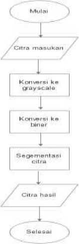
Figure 1. Flowchart
-
2.3. Grayscale imagery
The first step in image preprocessing is to convert the input image to a grayscale image. This process is an image processing process to convert color images that have a matrix value of red, green, and blue respectively into grayscale images. Based on testing the sensitivity of the human eye to color, grayscalling is done by the weighted method, as in equation (1) [8].
= ((0.3 * red) + (0.59 * green) + (0.11 * blue)) (1)
This method reduces the contribution of red and blue that arise and provides a greater contribution to green. The contribution value given to each color is 30% red, 59% green, and 11% blue.
-
2.4. Binary Image
The second stage is changing the grayscale image to binary image. Binary images are digital images that have only two possible pixel values, namely black and white. Globally, every pixel in the image is mapped into two values, namely 1 and 0, with the development function as in
equation (2):
1, f^)< T fB i, j )
(2)
0, lainnya
-
2.5. Image Segmentation
The third stage is the stage which aims to divide the entered image and take part of the important image. In the image segmentation process, the Horizontal projection method is used and then followed by the Connected Component Labeling (CCL) method.
Horizontal projection method will produce symbols or objects in the form of horizontal histogram lines. This method is based on the profile of the projection which is a data structure used to store a number of black pixels which are objects when an image is projected through the x-axis. This method is often used in character segmentation in Latin writing.
The next segmentation process is carried out using the connected component labeling (CCL) algorithm. The CCL method is a method that can be used to classify regions or objects in digital images. This algorithm applies the pixel connectivity theory of images. All pixels in a region are called connected or have relations if they adhere to the rules of adjacency or "proximity" pixels. This pixel proximity rule makes use of the proximity of one pixel to another pixel. Therefore, every pixel that is connected basically has an adjacency with each other because it has a neighbor or neighbor relationship. Neighbors must have a length or distance of 1 unit or be directly between one pixel and another without any intermediaries [9].
According to Gonzales and Woods [10] there are two kinds of connectivity used in 2dimensional images, namely 4-Connected Neighboard and 8- Connected Neighboard. 4-connectivity steps viz
-
a. A pixel is searched, starting from the matrix row to the column until a different pixel value (p) is found.
-
b. Once a different pixel value is found, it will be checked for each neighbor from pixel p, left and top.
-
c. Both pixels of neighboring p are 0, then they are given a new label or label.
-
d. If the two pixels of the neighbor p have a value of 1, then mark one of the neighboring pixels on p and make note that the two different marks are equivalent.
The 8-connectivity steps are:
In principle, the steps in 8-connectivity are the same as 4 connectivity, but there is only a slight difference, that is, when searching for each line if 4-connectivity pixel value p has been found, then what is connected is above and left. But in 8-connectivity if the value of p has been found it will connect each pixel by checking from the top, left, diagonally above left and diagonally above right. With the following steps:
-
a. If all four of the neighboring pixels are zero then give a new sign to p.
-
b. If only one of the neighboring pixels has a value of 1 then mark the neighboring pixel at p.
-
c. If two or more neighboring pixels that have a value of 1 then give one of the signs on p,
then all the signs of the neighbor that have value of 1 are equivalent.
The final process of 4-connectivity or 8-connectivity is to re-examine or scan images and replace each mark with an equivalent class mark.
-
2.6. Rule base
The next process carried out after segmentation by the CCl method is to position the results of the CCL segmentation that have been obtained following the rules of reading quadratic equations.
To differentiate between square numbers and base numbers, the coordinates of each image of the segmentation result will be taken into account. Will be initialized a condition where numbers will be identified as squares or basic numbers.
Furthermore, the results of recording the coordinates of the results of the segmentation will be stored in a table that has been made to determine the position of the numbers.
In this process, the program's accuracy level will be tested in segmenting the handwritten equation quadratic image using the Connected Component Labeling (CCL) method. The value of the level of accuracy can be calculated using equation (3) [11].
P(N) = M . 100%
(3)
N
Information :
P (N) = Accuracy level
I_N = Amount of data successfully segmented
N = Total amount of data
Research on segmentation to determine how to read quadratic equations with the Connected Component Labeling algorithm is implemented using the Matlab programming language.
The data used is handwritten data expression quadratic equations written on paper that has been provided. Example results from the respondent's handwriting that looks like the picture below:
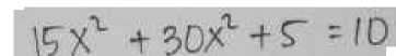
Figure 2. Original Image
In general, the process that was developed in building this system is the first, receiving input image of a mathematical quadratic equation obtained through the process of scanning (scans) the respondent's hand. Furthermore, the inputted image is then processed by grayscale prepossessing, and binaryization. The results of the prepossessing process are then carried out horizontal projection segmentation and then carried out using the Connected Component Labeling (CCL) method.
IWt +30λ1+f ^'D
Figure 3. Grayscale Imagery

Figure 4. Binary Image
Figure 5. Binary Image Inversions
Figure 7. Horizontal Projection Results
≡1ιs^^!aa.JS
Figure 8. CCL Segmentation Results
Figure 6. Horizontal Projection Plot
Figure 3 is an input loop in the form of an expression of a mathematical quadratic equation. Figure 4 is the result of grayscaling the original image and produces a grayscale image. Figure 5 is a binary image where object pixels will be 0 (black) and background pixels 1 (white) and 5 images are inverses of binary images which will cause object pixels to be 1 and background pixels to 0. Next Binary image inverses will enter the process of Segmentation with Horizontal projection and produce a plot like in a 6 image and produce a projection image as shown in Figure 7. Figure 8 is the image of segmentation results using the Connected Compont Labeling (CLL) Method.
Furthermore, the results of segmentation will be included in the rule base so that it can identify the quadratic equations of the input image. From the process that has been carried out in accordance with the proposed method, producing segmented imagery from quadratic equation images. The results of segmentation of the original image given in Figure 3a will be entered into the table provided to determine the position of the quadratic equation, can be seen in the table below:
Table 1. Segmentation Results
|
Posisi |
Blok 1 |
Blok 2 |
Blok 3 |
Blok 4 |
Blok 5 |
Blok 6 |
Blok 7 |
Blok 8 |
Blok 9 |
Blok 10 |
Blok 11 |
Blok 12 |
Blok 13 |
Blok 14 |
Blok 15 |
|
1 |
0 |
0 |
0 |
1 |
0 |
0 |
0 |
0 |
1 |
0 |
0 |
0 |
0 |
0 |
0 |
|
2 |
1 |
1 |
1 |
0 |
1 |
1 |
1 |
1 |
0 |
1 |
1 |
1 |
1 |
1 |
1 |
In the table 1 displayed the division of positions from the results of segmentation where position 1 is the position of the rank and position 2 is the position of the basic elementary numbers. When block 1 is 1 in the first position, the block is a rank. And if the block is 1 in position 2, then the block is a basic number.
In this research, segmentation and stroke grouping are generated which will produce groups representing single symbols. As for some of the data that I have tested that looks like the table below:
Table 2. Test Results
|
No |
Original Image |
Result | ||
|
Number of rank objects detected |
The number of base number objects detected |
Information | ||
|
1 |
y? * χ 4 ■ ∙ 5 |
1 |
8 |
succeed |
|
2 |
7 Xv 45X4 r; ∑ 15 |
1 |
11 |
succeed |
|
3 |
r. - . - |
1 |
12 |
succeed |
|
4 |
lςy ∙*∙ ⅛i⅛^*f 1W |
2 |
13 |
succeed |
|
5 |
√y + 5X 4 3 - ^ |
1 |
10 |
succeed |
|
6 |
⅛Xi 4 ^X 4'4 - C> |
1 |
10 |
succeed |
|
7 |
JJL ^ r 15 >'∙*l. ' U |
2 |
15 |
succeed |
|
8 |
⅛τ t 5X 43 - 4 |
1 |
10 |
succeed |
|
9 |
7⅛* v 9Xl t T∙ 7 |
2 |
10 |
succeed |
|
10 |
√cκτ ' 3□xt 3 • U |
1 |
13 |
succeed |
The table above is the result of some data that has been tested on the program. From 50 quadratic equation data consisting of 600 symbols tested, the results show that there is a damaged image so that the segmentation data becomes less accurate. Of the 600 symbols tested, the number of symbols successfully segmented was 588 symbols. The segmentation process and grouping of strokes that will produce groups representing a single symbol are carried out resulting in an accuracy rate of 98%.
Based on the results of tests conducted, the conclusion that can be drawn is the process of segmentation of handwritten image expression of mathematical quadratic equations with the Connected Component Labeling method achieving a success rate of 98% of the 50 quadratic equation data consisting of 600 symbols tested. Segmentation failure is more caused by damaged original images caused by intermittent writing during the writing process.
References
-
[1] Alvaro, F., & Benedi, J. M. (2011, September). Recognition of printed mathematical
expressions using two-dimensional stochastic context-free grammars. In 2011 International Conference on Document Analysis and Recognition (pp. 1225-1229). IEEE.
-
[2] Gonzalez, Rafael C., dan Richard E. Woods. 2008. Digital Image Processing 3rd
Edition. Upper Saddle River, NJ, USA: Pearson.
-
[3] Akbar, R., & Sarwoko, E. A. (2016). Studi Analisis Pengenalan Pola Tulisan Tangan
Angka Arabic (Indian) menggunakan Metode K-Nearest Neighbors dan Connected Component Labeling. Dinamika Rekayasa, 12(2), 45-51.
-
[4] Mardiana, T., Nyoto, R. D., & Nasution, H. 2011. Pengenalan Plat Nomor Kendaraan
Menggunakan Metode Connected Component Labeling Dan K-Nearest Neighbor.
-
[5] Toyozumi, K., Yamada, N., Kitasaka, T., Mori, K., Suenaga, Y., Mase, K., &
Takahashi, T. (2004, August). A study of symbol segmentation method for handwritten mathematical formula recognition using mathematical structure information. In Proceedings of the 17th International Conference on Pattern Recognition, 2004. ICPR 2004. (Vol. 2, pp. 630-633). IEEE.
-
[6] Koschinski, M., Winkler, H. J., & Lang, M. (1995, May). Segmentation and recognition
of symbols within handwritten mathematical expressions. In 1995 International
Conference on Acoustics, Speech, and Signal Processing (Vol. 4, pp. 2439-2442). IEEE.
-
[7] Garain, U., & Chaudhuri, B. B. (2004). Recognition of online handwritten mathematical
expressions. IEEE Transactions on Systems, Man, and Cybernetics, Part B (Cybernetics), 34(6), 2366- 2376.
-
[8] Salomon, D. (2011). The computer graphics manual. Springer Science & Business
Media.
-
[9] Yudhistiro, K. (2017, September). MENGHITUNG OBYEK 2D MENGGUNAKAN
CONNECTED COMPONENT LABELING. In Seminar Nasional Sistem Informasi (SENASIF) (Vol. 1, No. 1).
-
[10] Gonzalez. R & Woods R.E. (1992). Digital Image Processing, Addision- Wesley
Publishing Co.Inc.
-
[11] Kohavi, Ron, dan Foster Provost. 1998. “Glossary of Term : Special Issue on
Applications of Machine Learning and the Knowledge Discovery Process.” Machine Learning (Kluwer Academic Publishers) 30: 271-274.
291
Discussion and feedback