Room and Laboratory Equipment Lending Based On Smartphone Application Using QR Code Technology
on
Journal of Electrical, Electronics and Informatics, Vol. 5 No. 2
57
Room and Laboratory Equipment Lending Based On Smartphone Application Using QR Code Technology
Yandi Kurniawan1
D-3 Electronic Engineering
Bandung State Polytechnic
Bandung, Indonesia
yandi.kurniawan.tele18@polban.ac.id
The main problem in this research is dependency lab activities on the presence of a technician and complicated administrative process which take five procedure stages of lending at D3 and D4 Electronic Engineering polban. This research aims to create an equipment that is able to eliminate the dependency of the presence of technician, and to reduce the complicated administrative process. The QR code technology is the method used in this research to control the opening of lab doors and equipment cupboards by scanning the QR code with a mobile application. The result of this research show that the procedure borrowing of equipment facilities can be shortened from five procedurals to three procedurals. The QR Code information is able open the door of the room and laboratory cabinets by inputing password that been set at the database and able to borrow equipment that is integrated with the automatic recording of borrowing equipment.
Index Terms- QR Code, Laboratory, Scan, Loan Procedural.
-
I. INTRODUCTION
The laboratory is a room equipped with tools for teaching purposes [8]. The laboratory functions as a place to apply scientific theory, theoretical testing, test proof, research and job training. [9]. The pandemic has caused laboratory borrowers to not be directly accessible to conduct practicums, due to the vulnerability of technicians, students and lecturers in the transmission of the covid-19 virus. In addition, practical learning is strictly regulated with a long procedure, namely five stages of the loan procedure, starting from the process of borrowing tools to setting up the laboratory schedule.
The pandemic conditions and the lengthy procedures for borrowing laboratory facilities have caused the laboratory occupancy rate to be very high because the number of students who can use laboratory facilities at one time is very limited. Students must wait in line to get a practicum schedule.
Every single laboratory in the D3 and D4 study programs in Polban electronics engineering is managed by a technician, the current problem is that the number of technicians is less than the existing
laboratories, this makes it difficult for technicians if several laboratories are used at the same time.
Data collection on borrowing tools and learning modules requires the presence of a technician. In addition to being susceptible to transmission, technicians also find it difficult to provide equipment borrowing services for different laboratories.
Data collection on borrowing laboratory learning tools and modules is still done manually. This method is prone to data collection errors at the time of borrowing and returning.
Data collection on borrowing tools and learning modules manually cannot detect the feasibility of the equipment, making it difficult to repair and calibrate laboratory equipment at the end of the semester.
The keys to each laboratory are managed by a technician. This makes it difficult for students and lecturers if there are technicians who are not present. This final project aims to create a system for borrowing equipment in a smartphone applicationbased laboratory. The working principle is that students can borrow laboratory facilities without the need for the presence of technicians, this final project can shorten the procedure for borrowing laboratory facilities into three stages. The opening of laboratory doors and cabinets uses a QR code, which will direct
the mobile application to validate the password that has been set in the database. Equipment borrowing uses QR Code scanning which has been integrated with digital recording.
-
II. METHODS
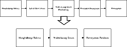
The design flow diagram is designed to achieve the goal, so that the final project can be more structured. The diagram in Figure 1 shows the design of this final project.
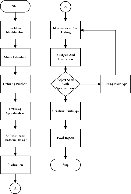
Figure 1
The flow chart in Figure 1 simplifies the sequence of work from beginning to end, with an outline explanation as follows:
-
1) Literature Study
This stage is done by collecting information and data that will be used in scientific documents for the final project, such as the method of making the application, the design of the circuit that will be used in accessing cabinets and doors in the laboratory, knowing the borrowing method that will be applied in the application, then studying how to integrate software with hardware, then learn how IoT principles can be applied in making this final project.
-
2) Design
In the design phase, the design of the specifications is determined and the block diagram of the system as a whole is designed, the design of mechanical elements, electronics, programming algorithms, wireless communication between the microcontroller and the smartphone application and the user interface display. Perform the design of the display that will be applied to the mobile application.
-
3) Realization
This stage is carried out for the realization of system block diagrams, realization of electronic, mechanical elements, algorithm design into programming languages, realization of wireless communication between microcontrollers and smartphone applications, and realization of user interfaces on mobile applications.
-
4) Measurement and Testing
This stage is carried out to test the functions that have been realized and make improvements to the test results so that the realized system can be made according to specifications.
-
5) Analysis and Evaluation
This stage is carried out to analyze the prototype according to the theories and evaluate the prototype according to the specifications.
-
III. RESULT AND DISCUSSION
A clear presentation of experimental results obtained, highlighting any trends or points of interest. The results should not be repeated in both tables and figures. The discussion should relate to the significance of the observations. If the content contains sub-chapters, it must be arranged in the following format.
The realization and testing of the electronic aspect is divided into 4 parts, namely the limit switch, microcontroller, relay and solenoid lock door section, and the overall test, with the test results in accordance with the electronic specifications.
The wiring diagram of the electronic system is shown in Figure 2. TP 1 to TP 4 are test points that will be used as test points for voltage measurements in Table 1 to Table 5.
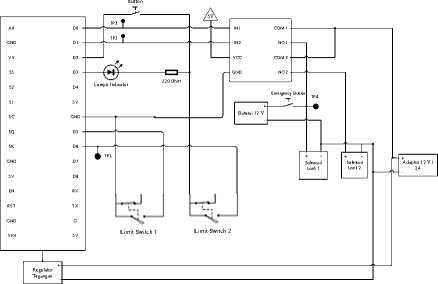
Figure 2
A.1 Nodemcu Microcontroller ESP8266
The use of the microcontroller is as a data processor, the data is taken from the database, the data is in the form of numbers 0 and 1, the test carried out is to connect the microcontroller to the internet network, then the microcontroller takes data from the database, the data is in the form of numbers 0 and 1, then the data will be converted into a voltage by the microcontroller to input the relay voltage as an actuator driver, namely the solenoid lock.
Table 1
|
Database reading |
Test Point |
Voltage (V) |
Indicator Lamp |
|
Logic door 1 |
TP2 |
3.3 |
Light up |
|
Logic door 0 |
TP2 |
0 |
Off |
|
Closet logic 0 |
TP3 |
3.3 |
Off |
|
Closet logic 1 |
TP3 |
0 |
Light up |
Table 2
|
Door Condition |
Test Point |
Voltage (V) |
Database response |
|
Close |
TP2 |
3.3V |
Door status → closed |
|
Open |
TP2 |
0V |
Door status → Open |
voltage of 3.3V. The indicator light serves as a marker that the solenoid lock has been opened.
Based on Table 2 the microcontroller can be connected to the internet, as evidenced by changes in the status data of doors and cabinets in the database.
A.2 Overall Electronic System Test
Overall electronic system testing is done by simulating unlocking by scanning a QR code. QR scanning is done using a smartphone application, when the password input matches the password in the database, the logic of the door in the database will change, from 0 to 1. The microcontroller will convert the string value "1" into a voltage of 3.3V, Voltage 3.3V serves as a trigger for relays (drivers).
The limit switch that functions as a switch is placed at the door, if the COM foot limit switch is connected to NO, the microcontroller will detect 0V voltage, the microcontroller will then change the status in the database so that the door status value is from "Open" to "Closed". The smartphone application will process this data change into door information on the Monitoring feature.
-
B. Realization and Testing of Software Aspects
Place figures and tables at the top and bottom of columns (if possible). Avoid placing them in the middle of columns. Large figures and tables may span across both columns. Figure captions should be below the figures; table heads should appear above the tables. Insert figures and tables after they are cited in the text. Use the abbreviation “Fig. 1”, even at the beginning of a sentence.
-
B.1 Application User Interface
Making a mobile application using Flutter, the test carried out is to open the application and observe whether the created display contains all the features contained in the specifications, namely information features, for details, see Figure 3
Based on Table 1 the microcontroller functions as a data processor, the results of data retrieval from the database in the form of string data values are converted into physical quantities in the form of a
Figure 3
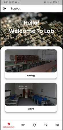
There are 2 features in making a mobile application, namely the student (user) version and the technician version, testing is carried out by testing the function of each feature, here are the differences between the two versions:
-
1. The technician application has all the features, namely lending features, information, databases, changing passwords and changing accounts, and direct monitoring features
-
2. The student application only has 2 features, namely the information feature and the loan feature
Table 3
|
Code |
Info |
QR Code |
Output | ||
|
ppa |
Analog Lab Door |
HtiH H⅜ | |||
|
pla |
Analog Cabinets |
HSH | |||
|
Pld |
Digital Cabinets |
EtiS Siffi | |||
|
1 |
ID : 1 Lokasi : Lab Analog |
I |
CΞD ^zzr*** |
|
Nama Alat : Oscilloscope Digital | |||
|
2 |
ID : 2 Lokasi : Lab Analog Nama Alat : Power Supply Analog |
bee ⅛⅛ |
Bs—■ |
|
3 |
ID : 3 Lokasi : Lab Analog Nama Alat : Multimeter Digital |
S^B 0≡ |
^≡∑__,1 |
|
4 |
ID : 4 Lokasi : Lab Analog Nama Alat : Modul H- Bridge |
ESE ⅛ |
>M>∙><mz. |
|
5 |
ID : 5 Lokasi : Lab Analog Nama Alat : Oscilloscope Analog |
SgS B⅛⅛ |
Q —- |
|
6 |
ID : 6 Lokasi : Lab Analog Nama Alat : Multimeter Analog |
^ |
A ~~"-∙ |
|
7 |
ID : 7 Lokasi : Lab Analog Nama Alat : Power Supply Digital |
t<t*r∏∙o*∙< | |
|
8 |
ID : 8 Lokasi : Lab Mikro Nama Alat : Multimeter Digital |
SfiS | |
|
9 |
ID : 9 Lokasi : Lab Mikro Nama Alat : Multimeter Analog |
H0 |
O ≡≡r^ |
|
10 |
ID : 10 Lokasi : Lab Mikro Nama Alat : Arduino |
HBH |
∣,' ⅛⅛ho |
|
11 |
ID : 11 Lokasi : Lab Analog Nama Alat : Modul IC |
S^S |
Based on the test results of table 3 each QR code will have a different output, if the information in the QR code is to open a door or cupboard, it will direct the smartphone application to the password panel, if the information in the QR code is to borrow equipment, the loan will be stored on smartphone applications and databases.
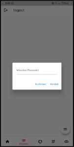
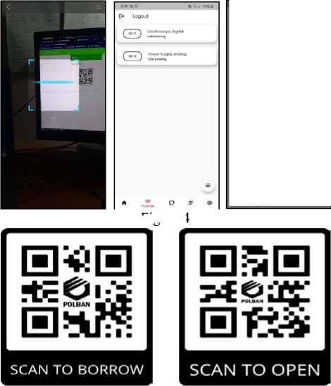
Figure 5
Figure 4
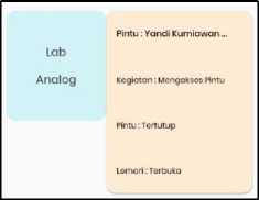
⅛- Status - Analog
Kegiatan: 'Mengakses Pirtu"
Lemari: ' Ierbuka"
Peminjam: Yandi Kurniawan 2021-0/-05 20:49:14.325459
Pintu: "IcrtJtup'
IogicLcmari: θ
IogicPintu: 1'
Figure 6
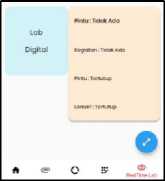
Figure 4 is the realization of the QR code feature, there are two outputs, namely, a password panel and equipment borrowing. Figure 5 is the realization of the QR code that will be attached to equipment and
doors/cupboards in laboratory facilities. Figure 6 is the realization of the realtime database that will be used in the data processing as a monitoring feature by the smartphone application, and processed by the microcontroller into a voltage form.
Table 4
|
Input |
QR Code |
Output |
description |
|
Correct Password |
Cabinets |
Cabinets Open |
Input = database |
|
Door |
Door Open | ||
|
Wrong Password |
Cabinets |
Cabinets Lock |
Input != database |
|
Door |
Door Lock |
Table 4 shows that if the password is entered incorrectly, the solenoid lock will not open, and vice versa if the password is correct, this means that if the user does not have access from a technician, he will not be able to access the laboratory.
L - : Q . ■,.
+ Add document + Stort collection
Pawwril > +Mdritw
Password V
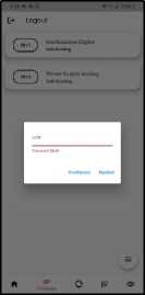
Figure 8
Figure 7
Figure 7 is the realization of the password database which will be the user's reference to unlock the door/cabinet. Figure 8 occurs when the entered password does not match the password that has been set in the database.
Table 5
|
Input QR |
Monitoring Features |
|
Borrower identity |
Displays borrower identity |
|
Borrowing lab Equipment |
Showing the use of borrower's tools |
|
Access the door/cabinet |
Showing the activities of the borrower |
Table 5 shows activities in the laboratory when the borrower uses the laboratory, it will be monitored by technicians on the smartphone application
initial display is Figure 11, when pressed it will enter the tool description.
Figure 13 shows the description of the equipment borrowed by the borrower. Figure 12 is a complaint from a borrowed tool, this page will appear when the user presses the complaint button on the borrowed tool description page or Figure 13. Figure 14 is the realization of the borrower database shown in Figure 11.
Table 7
Figure 9 Figure 10
Figures 9 and 10 are the realization of monitoring the laboratory room directly on the smartphone application.
Table 6
|
Input QR |
Database application |
|
Equipment loan |
Information on the date of the loan, the identity of the borrower, the tools used, the evaluation of the use of the equipment |
Based on the test of Table 6 the identity and description of the borrower will appear in the database feature in the smartphone application, with the information displayed, namely, identity, borrowed laboratory, date, equipment borrowed, and complaints of borrowed equipment.
|
Testing |
Experimental Results | ||
|
Input |
Cloud database |
Student application | |
|
Account creation for new students |
Email & password |
New account registered |
Account can be used |
|
Change the password for access to doors and laboratory cabinets |
Password |
Old password changed to new password |
Can access the door if you enter the right password |
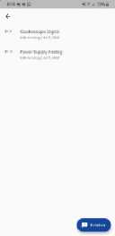
Figure 11

Figure 12
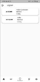
Figure 13
Based on the test of Table 7 the account that has been created will be registered in the database, then it will become email and password information that can be used to access smartphone applications
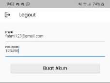
Figure 15
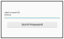
Figure 16
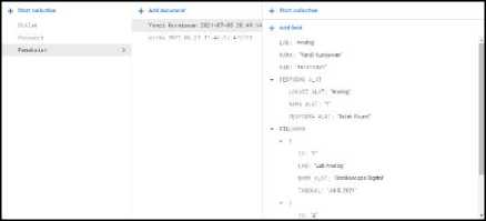
Figure 14
Figure 11 ; 12 ; 13 is the realization of the database feature displayed on the smartphone application, the
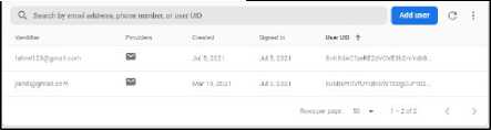
Figure 17
Figure 15 is the realization of the account creation feature, to create an account the technician must enter an email and password. Figure 16 is the realization of the password change feature. Figure 17 is the realization of the account database that has been created.
Testing of the entire software is carried out in order to be able to observe the work of the entire system from the software, the test is carried out by simulating room borrowing by scanning a QR code, then simulating borrowing equipment by scanning a QR code. Door locks and laboratory cabinets will open if the password
entered matches the password in the database. The identity of the borrower, the activities carried out by the borrower, the condition of the doors and cabinets in the laboratory will be displayed in the monitoring feature. Borrowed equipment will be displayed in the database feature in the smartphone application. The information displayed includes: 1) Borrower Identity
-
2) Borrowed laboratory
-
3) Borrowing Date
-
4) Details of equipment borrowed
-
5) Equipment Performance Complaint
Equipment borrowing activities will also be displayed in the monitoring feature.
-
B.4 Realization and Testing of Mechanical Aspect
The realization and mechanical testing is done by placing the equipment in a box that has been designed as a microcontroller case. The box contains an electronic system that functions as a regulator for opening doors and cabinets in the laboratory and also as a communication line to find out the status of the doors in the laboratory, for details, see Figure 18; Figure 19 ; Figure 20; Figure 21 ; Figure 22; Figure 23; Figure 24
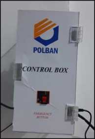
Figure 18
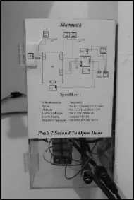
Figure 19
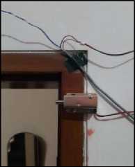
Figure 20
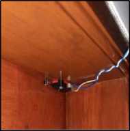
Figure 22
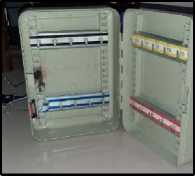
Figure 23
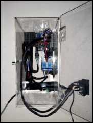
Figure 21
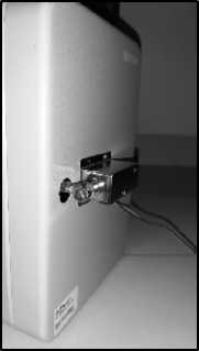
Figure 24
The test results are that the tool works in accordance with FRS, opening doors and cabinets can be done simply by scanning a QR code, then direct monitoring can be viewed using a smart phone application, and equipment borrowing only uses a QR code.
Table 8
|
Function Requirement System |
Status |
|
The app requires a login to access. |
Realized according to table |
|
Applications can unlock doors and lock cabinet doors using a QR code as access, then enter a password to unlock. |
Realized according to table |
|
Applications can borrow tools by scanning a QR code. |
Realized according to table |
|
The mobile application can record the identity and loan of the laboratory and its equipment. |
Realized according to table |
|
Mobile applications can monitor activities in the laboratory in real-time. |
Realized according to table |
based on the analysis of the test results, the laboratory loan procedure can be minimized into three procedures by eliminating the procedure for matching the technician's picket schedule with the loan schedule, and recording equipment borrowing manually.
The role of the presence of technicians in the laboratory can be eliminated by the QR Code scanning method, and the monitoring feature on the smartphone application, an alternative to the role of the presence of technicians is described in more detail in Table 9
Table 9
|
Technician Presence Role |
Substitute |
|
Store and manage keys to unlock laboratory rooms |
Unlock laboratory doors by scanning QR Code |
|
Store and manage keys to unlock Equipment cabinets |
Unlock tools cabinets by scanning a QR code. |
|
Coordinate and store data collection of equipment borrowed |
Perform data collection on equipment borrowing automatically |
|
Monitoring the laboratory room |
Presenting the laboratory room monitoring feature on the smartphone application |
IV. CONCLUSION
After carrying out the stages of the final project, the conclusions of this final project are: 1) The procedure for borrowing laboratory facilities was shortened from five procedures to three procedures.
-
2) The presence of technicians in the laboratory can be eliminated by scanning the QR code method on borrowing laboratory facilities.
-
3) The smartphone application can digitally collect laboratory facility loan data.
-
4) The smartphone application can unlock doors and laboratory cabinets by using a QR code when entering a password that matches the database.
-
5) The smartphone application can borrow equipment by scanning a QR code.
-
V. REFERENCES
-
[1] M. Clow, Learn Google Flutter Fast, 2019.
-
[2] P. S. A. W. Rivepiboon, “Framework For Fast Building Software Requirements Specification,” Journal Of Information Systems, Vol. 1 Dari 2 Volume 9,, No. Issue 1, 2013.
-
[3] R. Halliday, Fundamentals Of Physics, Clevelend: John Wiley & Sons, Inc,, 1970.
-
[4] P. T. M. Z. Sachin Kumar, “Internet Of Things Is A Revolutionary Approach For Future Technology Enhancement: A Review,” Journal Of Big Data, Vol. 6, No. 111, 2019.
-
[5] A. P. Andreas Kamilaris, “Mobile Phone Computing And The,” Internet Of Things Journal, 2016.
-
[6] J. H. Chang, “An Introduction To Using QR Codes In Scholarly Journals,” Sci Ed, Vol. 1, No. 2, Pp. 113-117, 2014.
-
[7] B. W. Gunther Gridling, “Embedded Computing Systems Group,” Dalam Introduction To Microcontrollers, Vienna, 2007.
-
[8] KBBI, Kamus Besar Bahasa Indonesia, 2016.
-
[9] A. Emda, “Laboratorium Sebagai Sarana Pembelajaran Kimia,” Lantanida Journal, Vol. 5, No. 1, 2017.
-
[10] Oracle, “Https://Www.Oracle.Com/,” Oracle, [Online]. Available:
Https://Www.Oracle.Com/Database/What-Is-Database/. [Diakses 30 July 2021].
Discussion and feedback