Automation Rice and Water Filling System on Rice Cooker Via Internet of Things
on
Journal of Electrical, Electronics and Informatics, p-ISSN: 2549–8304 e-ISSN: 2622–0393
72
Automation Rice and Water Filling System on Rice Cooker Via Internet of Things
Fajry Adi Rahman1*, Josua Ronaldo Simanjuntak2, Elvino Simanjuntak3, Porman Pangaribuan4, Willy Anugrah Cahyadi5
-
1,2,3,4,5School of Electrical Engineering Faculty of Electrical Engineering, Telkom University
Bandung, Indonesia
fajryadir@student.telkomuniversity.ac.id
Abstract Working and doing activities often leave someone busy with no time to do other work, such as cooking rice. Cooking rice is easy, but due to time constraints often make someone not have time to do it. This is because to cook rice in the commonly used rice cooker must be done manually. Starting from pouring rice into the pan, measuring the composition of rice and water accordingly, to pressing the warm mode button to cook button. So, to cook rice, users must spend time on the sidelines of work or activities. Based on these problems, it is necessary to design a new system on rice cookers. A system that combines rice cookers, rice storage, and gallons of water in one device. In addition to the new system that was designed, all preparations for cooking rice which previously had to be done manually can now be done automatically which is entirely controlled using a smartphone via the application. The result of this final project is the percentage of the average accuracy of the load cell sensor in calculating the mass of rice that enters the rice cooker which is 97,22% with an average percentage error of 1,41%. The average accuracy of the flowmeter sensor in calculating the volume of water that enters the rice cooker is 97.76% and the average error is 0.97%. The average time needed for sending data from the application to the automation system is 253 ms.
Index Terms—Rice Cooker, Load Cell Sensor, Flow Meter, Internet of Things
Working and doing activities often leaves someone busy with no time to do other work, such as cooking rice. Cooking rice is easy, but due to time constraints often make someone not have time to do it. This is because to cook rice in the commonly used rice cooker must be done manually. Starting from pouring rice into the pan, measuring the composition of rice and water accordingly, to pressing the warm mode button to cook button. So, to cook rice, users must
spend time on the sidelines of work or activities.
In previous studies, an innovative smart rice cooker was conducted using the Wi-Fi communication protocol and the MQTT message exchange protocol with the automatic filling of rice and water [1]. But the innovation of the smart rice cooker still has limitations, namely the open and close system of the rice cooker, the choice of the amount of rice that can be cooked is limited, and also the user still has to manually put rice into the rice cooker from the storage
container
Based on the existing problems, a new system in the rice cooker is needed. A system that combines rice cookers, rice luggage, and gallons of water in one device. Also, the new system designed all preparations for cooking rice which previously had to be done manually can now be done automatically, which is entirely controlled using a smartphone via the application.
So that with the new system, it is expected to provide convenience to users. Because users can cook rice without having to do it manually again, but just enough to use the application on a smartphone. Also, users can cook rice on the sidelines of activities or work from anywhere without time or distance constraints.
Mass is the amount of material contained in an object and is constant or unchanging. The basic unit of SI for mass is
kilograms (kg). The sensor that can be used in these measurements is a load cell sensor [2].
-
2.2 Density
There are various methods for measuring mass. One
method that can be used to calculate rice mass is through volume calculation with a density of 753 kg/m3, according
to equation (1).
m
(1)
-
2.3 Hall Effect
The Hall effect is the phenomenon of the flow of charge on a metal chip placed in a magnetic field. The deflection of charge flow causes potential differences between the sides of the chip called Hall potential. The Hall effect on metal chips arises because of the interaction of charges (electrons) that move with the magnetic field. The load has a Lorentz force F = q (v × B) which causes the charge to be deflected [3].
-
2.4 Strain Gauge
A strain gauge is a thin band of conductors that will rise their electrical resistance when stretched (positive strain/tension stress) and down when constricted (negative strain / compressive stress) [4]. This is because in the strain gauge there is a lattice that will change its resistance when under load. When given a load, the strain gauge lattice will shrink (compressed) causing the cable inside the strain gauge to be shorter and the lattice to be wider, so the resistance value decreases. Meanwhile, if not exposed to the load, the strain gauge will stretch (tension) causing the cable inside the strain gauge will be longer and the lattice will be narrower, so the resistance value will increase according to the equation (2).
I
r~pa
-
2.5 Load Cell Sensor
Load Cell Sensor is a sensor in which there is a strain gauge to change the load or force acting into an electronic signal [5]. This electronic signal can be either a voltage change or a current change depending on the type of load cell used. The load cell sensor in this system is used to count the rice that has entered the rice cooker.
-
2.6 Flow Meter
Flowmeter is a tool to measure the amount of flow rate of water from a fluid flowing in a pipe or open connection. This tool consists of the main device, which is referred to as the main tool and secondary aids. Flowmeter generally consists of two parts, namely the main tool and secondary aids. Flow meters are used in this system to measure the volume of water that has entered the rice cooker
The system framework is 71 cm long, 39 cm wide, and 96 cm high. The framework is divided into 4 parts, as follows.
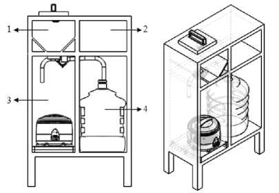
Fig 1. Framework design
-
1. Rice storage that can save ± 13 kg of rice.
-
2. Storage of several components related to system electronics.
-
3. Rice cooker with a 2-liter capacity, linear actuator, flow meter, and load cell sensor.
-
4. Place gallons of water with a 19-liter volume.
The material used to make the framework is aluminum hollow with a length of 2 cm and a width of 2 cm with a thickness of 0.4 mm. The choice of hollow aluminum is due to its light mass but has resistance in supporting heavy objects. In the framework that is made given the addition of 4 wheels in each leg, which is useful to facilitate the process of mobilization if you want to be moved. In the rice cooker section, there is a sliding feature, it is intended that the user can easily pull out the rice cooker.
3.2 Load Cell Sensor Placement
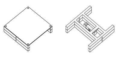
Fig 2. Load Cell Placement
load cell sensor is an important component in this system. Load cell functions to measure the amount of rice in the rice
cooker, it takes high accuracy of the load cell so the system can work well. So in the sensor placement design, the load cell sensor is placed in a frame in the form of the letter H or commonly called the H scale frame. It is intended that the load cell can hold and measure the mass of the rice cooker as
a whole because by using this framework the mass of the rice cooker can be measured accurately on all sides. The load cell sensor is placed in the middle of the framework bolts on both sides, so as not to change position. The material used for the skeleton is a 2 mm thick hollow iron equipped with an iron plate to cover the 20 mm thick frame. The framework has a length of 26 cm, width 26 cm, and night 5 cmApplicationn Design
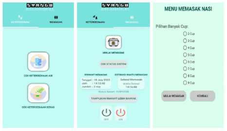
3.3 Aplication Design
master and slave can send data to each other. So that it supports the performance of all the required features, such as the process of checking the availability of rice and water.
The commands sent by the user on the android application will go to the MCU Node in the form of char data, the char will then be sent to Arduino Mega 2560. Data in the form of char received by Arduino Mega 2560 will then be sorted according to the cooking orders the user wants. The char will be compared with a list of commands for cooking in the Arduino program [7][8]. If after the char is compared to the list of cooking commands from 2 cups - 9 cups there are similarities, then the execution of the program for cooking will immediately be run by the system
Fig 3. Aplication Display
The application on a system that is designed is the most important thing so that the automation system designed can operate. Application designed based on Android and connected to the database. So that all user activities when using this application are all stored in a database such as a history of cooking rice that has been done. The application is designed called "Nyangu", the application consists of two layers, on the first layer there is an option to check the availability of water and the availability of rice in realtime The placement feature checks the availability of rice and water on the first layer so that before cooking rice the user knows in advance the availability of rice and water contained in the system. While on the second layer there is a rice cooker logo as a button to cook with a choice of the number of cups from 2 cups - 9 cups, then there is a history of cooking that has been done, estimated cooking time required, check the internet connection and on-off button from the rice cooker.
3.4 Data Transmission Design
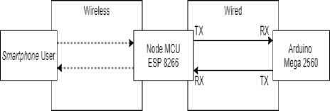
Fig 4. Data Transmission
So that the system can run the command IoT, 2 microcontrollers are used. The first microcontroller is ESP 8266, ESP 8266 functions as a WIFI module or an intermediary between the user and the system that will receive all commands from the user's mobile phone. Three orders can be received and sent ESP 8226 to the slave, namely cooking rice, checking the availability of rice, and checking the availability of water. All command data received by ESP 8266 will then be sent to Arduino Mega 2560 (slave). Arduino Mega 2560 which is the second microcontroller as the brain of the system that will run all the commands requested by the user. Data transmission communication between ESP 8266 and Arduino Mega uses UART serial communication [6]. UART type serial communication was chosen because it is easy in the operating system, the use of a small path, and between the
3.5 System Realization
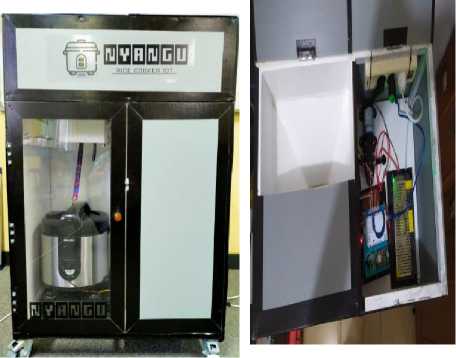
Fig 5. System Realization
The picture above is a tool that has been made. The tool that is made has full control using the android application. in the left picture is the whole tool, while in the right picture is the storage area for rice and electronic components.
-
3.6 Sensor Testing
Sensor testing aims to determine and calculate the percentage of errors, the percentage of average errors, and the percentage of accuracy of the sensors used in the system.
To calculate and find the percentage of errors on the sensor,
the equation is used.
% Error =
Actual Value - Read Value
Actual Value
×100% (3)
To calculate and find the average percentage error on the sensor, the equation is used
Σ | Testing Error |
Average Error = ---
Number of Test
(4)
To calculate and find the percentage of accuracy on the sensor, the equation is used.
% Accuracy = 100% — %∖ Highest Error | (5)
-
3.7 Testing of Load Cell Sensor and Flow Meter
The next test is testing the accuracy of the load cell sensor and flow meter on the system that has been designed. The test scheme is Figure 8. The Graph of Accuracy Load Cell Sensor carried out by
simulating the process of cooking rice from 2-9 cups, for each cup carried out 5 × testings with orders that are run from the Nyangu application, when the rice and water come out will be accommodated separately. So that after the rice enters the rice cooker, the rice and water can be removed again to be weighed using a digital scale so that the accuracy of the load cell and flow meter in the system can be known.
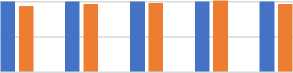
This test only takes samples when filling 2 cups of rice (300 grams of rice and 600 ml of water) with each test of 5 times.
Testing 2 Cups
350
i 200 Il Il Il Il Il
12345
Testing
-
■ Setpoint Value ■ Read Value
Fig 6. Chart of 300 g rice test result
The results of tests that have been carried out as shown in Figure 6, obtained an accuracy of 98,67% with an average error of 0,80%.
been determined, so that the ratio of 1: 2 between rice and water can be met.
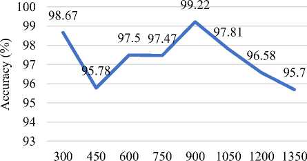
Load Cell Sensor Accuracy 2 Cups - 9 Cups
Mass of Rice (g)
-
3.7 Testing Application Features
Application testing aims to determine whether the application can give commands to the system, then the system can run commands properly according to the features contained therein. The first feature tested in the application is the cooking feature of 2 cups - 9 cups. Then for the second feature tested is the feature of turning off and turning on the rice cooker using the application. The results of the first test conducted in the Table 1.
Testing of 600 ml water
650
600
550
500
12345 Testing
■ Setpoint Value ■ Read Value
|
No. |
Command From The Application |
Execution by The System |
|
1 |
2 Cups |
Success |
|
2 |
3 Cups |
Success |
|
3 |
4 Cups |
Success |
|
4 |
5 Cups |
Success |
|
5 |
6 Cups |
Success |
|
6 |
7 Cups |
Success |
|
7 |
8 Cups |
Success |
|
8 |
9 Cups |
Success |
Figure 7. Chart of 600 ml water test result
The results of tests that have been carried out as shown in Figure 7, obtained an accuracy of 99% with an average error of 0,27%.
From the tests that have been carried out starting from 2 to 9 cups, the highest percentage of accuracy produced is 99.22% when testing 6 cups. As for the lowest accuracy percentage produced 95.70% when testing 9 cups. From the average percentage of accuracy generated overall, the resulting is 97.22%. Then for the average overall error generated is 1.41%. With the percentage value of accuracy and error generated, the load cell sensor can work well due to high accuracy, so that the implementation of the load cell sensor is right on the system made. With this result, the mass of rice released can be close to or equal to the mass that has
The next feature test is to turn on and turn off the rice cooker using the application, the test results obtained in the Table 2. Turn on and turn off the rice cooker using the application can work well. From 30 × attempts to turn on the rice cooker using the application, the system reliability reached 96.6% with only 1 × data failing. Whereas for 30 × attempts to turn off rice cookers using the application, the system reliability reached 100% with 0 × data failing. Then the average time needed for the application to send data to the system until the system runs the command is 253 ms. So that the application has been made to meet the target, both in terms of features and data delivery time.
TABLE II
Testing Application Feature for On-Off Rice Cooker
|
No. |
Command From The Application |
Condition of Rice Cooker |
|
1 |
ON |
ON |
|
2 |
OFF |
OFF |
TABLE III
Data Delivery Delay Testing
|
Menu |
Data Size (Bytes) |
30 × Data Sending |
|
Average Delay (ms) | ||
|
2 Cups |
44 |
215 |
|
3 Cups |
44 |
252 |
|
4 Cups |
44 |
206 |
|
5 Cups |
44 |
258 |
|
6 Cups |
44 |
255 |
|
7 Cups |
44 |
232 |
|
8 Cups |
44 |
240 |
|
9 Cups |
44 |
221 |
|
Average Overall Delay (ms) |
235 | |
The automation system added to the rice cooker has succeeded in automatically filling rice and water with a ratio of ± 1:2, turning on the rice cooker when starting cooking, , and can turn on and turn off the rice cooker which is entirely controlled using the IoT-based android application on the smartphone.
Acknowledgment
The author gratefully acknowledges the facility support for this research by Microprocessor and Interfacing Laboratory, Telkom University.
References
-
[1] M. A. Sutiono, “Rancang Bangun Smart Rice Cooker Menggunakan
Protokol Komunikasi Wi-Fi Dan Protokol Pertukaran Pesan MQTT,” Fak. Tek. DAN Inform. Univ. Multimed. Nusant., p. 9, 2016.
-
[2] M. H. A. Pratama, R. Satriatama, P. Pangaribuan, and D. Darlis, “Design and Implementation of Dispenser Water Volume,” Int. J. Res. Appl. Sci. Eng. Technol., vol. 8, no. I, pp. 171–174, 2020.
-
[3] Jacobus, Liefson, dan Dewi Krisna Gulo, "Rancang Bangun Teslameter Dengan Metode Induksi," JTI UKRIM, vol. 6, pp. 42-47, 2014.
-
[4] R. Debriand, M. Doloksaribu, and I. Damanik, “Rancang Bangun Timbangan Load Cell Tipe S Design of Weight Sensor Load Cell Type S,” vol. 40, no. 2010, 2018.
-
[5] A. Cipta, “Aplikasi Sensor Load Cell pada Purwarupa Sistem Sortir Barang,” IJEIS (Indonesian J. Electron. Instrum. Syst., vol. 4, no. 1, pp. 35–44, 2014.
-
[6] A. K. Gupta, A. Raman, N. Kumar, and R. Ranjan, “Design and implementationthe of high-speed universal asynchronous receiver and transmitter (UART),” 2020 7th Int. Conf. Signal Process. Integr. Networks, SPIN 2020, vol. 1, pp. 295–300, 2020.
-
[7] K. D. Kramer, T. Stolze, and T. Banse, “Benchmarks to find the optimal microcontroller-architecture,” 2009 WRI World Congr. Comput. Sci. Inf. Eng. CSIE 2009, vol. 2, pp. 102–105, 2009.
-
[8] O. Vermesan and P. Friess, “Internet of Things Strategic Research and Innovation Agenda,” Internet Things – From Res. Innov. to Mark. Deploy., p. 143, 2014. ICEE 2019 - 27th Iran. Conf. Electr. Eng., pp. 249–252, 2019.
Discussion and feedback