Induction Motor Monitoring System Base on Fuzzy Logic Controller
on
Journal of Electrical, Electronics and Informatics, Vol. 4 No. 1, February 2020
15
Induction Motor Monitoring System Base on Fuzzy Logic Controller
RS Hartati1, IBG Manuaba2, M Mataram3
1,2,3 Department of Electrical Engineering Faculty of Engineering, Udayana University Badung - Bali, Indonesia
1rshartati@gmail.com, 2ibgmanuaba @unud.ac.id, 3mademataram@unud.ac.id
Abstract Squirrel cage induction motor is an AC electric motor that is most widely used in industry. This type of motor is chosen because it does not have a commutation brush, and its construction is strong, so it can withstand large, easy flow surges for repair and maintenance. The problem that often occurs is the imbalance of supply voltage which causes motor efficiency to decrease. An imbalance of voltage will result in a current not equal. As a result of phase currents that are much larger than other phases result in an increase in temperature and speed on the motor. This research was conducted to monitor the induction motor so that it can determine the condition of the motor when receiving a voltage imbalance.
The method used in the induction motor condition monitoring system is the fuzzy logic method. Parameters that can be monitored are categorized into three conditions: normal (good) motor condition, damage (serious) and serious damage.
Index Terms— Squirrel cage induction motor, Voltage Imbalance, Fuzzy Logic
An electric motor is an electromagnetic machine that converts electrical energy into mechanical energy. This mechanical energy is used to rotate or move such as electric drill, fan, conveyor, pump and others. In general, the electric motor is divided into 2 types, namely direct current electric motor (DC) and alternating current (AC). AC motors are more widely used than DC motors because AC currents can be generated easily and distributed at a lower cost. In addition, it has advantages in terms of care. Squirrel cage induction motor is a type of AC motor that is the most widely used, because it does not have a brush and commutation, so it can withstand large enough surges.
The problem that often occurs in the operation of an induction motor is voltage imbalance. Ideally, the voltage supplied by a 3 phase induction motor is sinusoidal and balanced. The balanced state is defined as the three voltage vectors being equal and forming 120o angles to each other. While the condition is not balanced as the three vectors do not form an angle of 120o, the three vectors are not equal. Voltage imbalances always occur caused by the loading of one phase of a low voltage network [1].
Voltage imbalance causes current imbalances, so the
efficiency of the induction motor decreases and heat increases [2]. To prevent efficiency and excessive heat that cause damage, a monitoring system based on fuzzy logic is created. The advantages of fuzzy logic have the ability in the process of reasoning linguistically, so it does not require mathematical equations of the objects to be monitored. A similar study was conducted by [3] with a squirrel cage rotor induction motor with 4 poles connected to delta (Δ). The results of experiments for interference with induction motors can be diagnosed using fuzzy logic methods. The difference between this research and the previous one lies in fuzzy logic design, so that it gets better performance.
-
II. METHOD
-
2.1 Squirrel Cage Three Phase Rotor Induction Motor
-
Squirrel cage motor section has a simple construction. The stator core on the three phase squirrel cage motor is made of fabricated steel plate layers. The coil of the stator coil is placed in a stator groove separated by 120O electric. This phase coil can be connected in connection with delta (∆) or star (Y). The equivalent circuit of the induction motor is shown in Figure 1. The slip is defined as follows [4]:
Ns-Nr Ns
Corresponding author RS Hartati – rshartati@gmail.com
Where Ns expresses the synchronous speed and Nr is the rotor speed. The negative sequence voltage will cause the rotating field to rotate at synchronous speed but in a counterclockwise direction. As a result, slips against negative sequence voltages are [5]:
-Ns-N
s? = — r = 2-s
2 -N
(2)
Because the slip s value is usually very small, close to zero, the negative sequence slip has a value close to two. As a result, the rotor impedance to negative sequence voltage will be very close to the motor impedance when short circuit. Therefore, large positive sequence impedances relative to negative sequences can be approximated by the equation
£1 _ !start
£2 rrunning
Or,
!2 _ — × !start
!1 V1 !_running
(3)
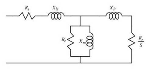
Fig. 1. Equivalent series of induction motors
Motor start currents usually range from 6 to 8 times full load current. Therefore, a 5% voltage imbalance will produce a current imbalance of between 30% and 40%. Because the rotor resistance to the negative sequence frequency current is greater than that of the positive sequence current, the power losses in the rotor will increase rapidly. In addition, additional heating in the stator and rotor will cause the age of the stator insulation to decrease rapidly.
-
2.2 Fuzzy Logic
The reasons for using fuzzy logic include: the concept of fuzzy logic is easy to understand with the mathematical concepts underlying fuzzy reasoning are very simple and easy to understand, very flexible [6], and [7]. Fuzzy logic tolerates data that is not right, able to model nonlinear functions that are very complex. Fuzzy logic can build and apply the experiences of experts directly without having to go through the training process, can work with conventional control techniques and based on natural language.
To model the monitoring of 3 phase induction motor
condition, the results of the research data are used as input parameters so that the output percentage of voltage and current imbalances is obtained which is useful for monitoring the condition of the 3 phase induction motor. The percentage imbalance provides information on the percentage imbalance of the voltage entering the 3 phase induction motor. So that with these parameters membership functions can be arranged from input / output and rule evaluation from fuzzy systems.
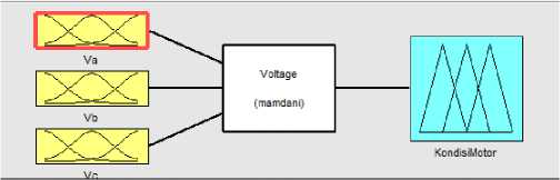
Fig. 2. Equivalent series of induction motors
The parameters Va, Vb, and Vc, represent input voltages in 3 phase induction motors and input parameters on fuzzy systems.
(4)
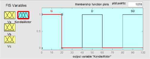
Fig. 3. Equivalent series of induction motors
Membership function outputs 3 phase induction conditions. Membership function is a curve that shows the mapping of input data points into its membership value often also called the usual membership degree having an interval of 0 to 1.
-
A. Membership input function.
The membership input function uses a trapezoidal curve representation because some points have a membership value of 1.
-
B. Membership function output.
Membership output function uses a representation of the shoulder shape curve because some variables do not change.
Make Rule Evaluation.
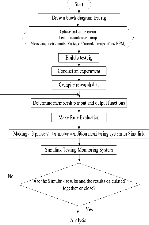
Rule evaluation of the 3 phase induction motor condition monitoring system is designed from experimental data and literature studies. Rule evaluation is represented by a natural language called IF-THEN rule. Making a monitoring system for 3 phase motor condition based on fuzzy logic using ATMEGA 2560 microcontroller
Stop

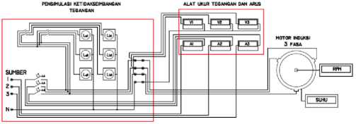
Fig. 5. Block diagrams and research test tools
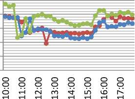
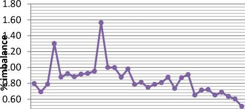
Results of Monitoring Voltage Imbalance on the Power Supply, fluctuations in imbalances that occur can be seen in the graphs in Figures 6 and 7.
230.0
225.0
of 220.0
O 215.0 >
210.0
205.0
—•— R
—•— S
—•— T
time
Fig. 4. A flow diagram for a multi machine
Fig. 6. Graph of voltage fluctuations
0.40
-
III. EXPERIMENT AND RESULTS
To obtain monitoring data used as fuzzy parameter data , a research test tool was made to monitor motor conditions. The test equipment of this study contains electricity sources, measuring instruments, and 3 phase induction motors. Block diagrams and research test tools can be seen in Figure 4.
0.20
0.00
oooooooooooooooo θ∞θ∞θ∞θ∞θf77θ∞θ∞θ∞ ∂∂HHtNcNrnfn⅛-⅛-ι½ιnΦωr×r×
time
Fig. 7. Graph the percentage of fluctuations in voltage imbalances
Seen in Figure above, the time of 10.45 and 12.30 has the highest voltage imbalance and the time range from 10.00 to 17.30 voltage imbalances under normal conditions. Nominal allowance for imbalance is 1% [8].
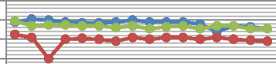
Monitoring of load motor by simulating voltage imbalance
The load given uses a magnetic power breaker. Motors are given 2 different loads to determine the effect on motor performance on each given load. Motor monitoring is loaded with 1.0 A current by simulating voltage imbalances. This monitoring is carried out in 64 monitoring
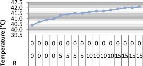
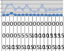
with a combination of simulating different voltage imbalances and each monitoring is given 5 minutes to get the temperature value on the motor. Graphs of monitoring results can be seen in figures 8 to 11.
222.0
220.0
218.0
216.0
> 214.0
QJ 212.0
0 5 1015 0 5 1015 0 5 1015 0 5 1015
O >
R
S
|
0 |
0 |
0 |
0 |
0 |
0 |
0 |
0 |
0 |
0 |
0 |
0 |
0 |
0 |
0 |
0 |
|
0 |
0 |
0 |
0 |
5 |
5 |
5 |
5 |
10 |
10 |
10 |
10 |
15 |
15 |
15 |
15 |
|
0 |
5 |
10 |
15 |
0 |
5 |
10 |
15 |
0 |
5 |
10 |
15 |
0 |
5 |
10 |
15 |
—•— R
—•— S
→- T
Load combination (W) T
Fig. 8. The graph of voltage results on monitoring of load motor with 1.0 A current by simulating voltage imbalances.
1.150
1.100
1.050
1.000
0.950
< 0.900

C φ

|
0 |
0 |
0 |
0 |
0 |
0 |
0 |
0 |
0 |
0 |
0 |
0 |
0 |
0 |
0 |
0 |
|
0 |
0 |
0 |
0 |
5 |
5 |
5 |
5 |
10 |
10 |
10 |
10 |
15 |
15 |
15 |
15 |
|
0 |
5 |
10 |
15 |
0 |
5 |
10 |
15 |
0 |
5 |
10 |
15 |
0 |
5 |
10 |
15 |
—•— R
—o— S
→- T
Fig. 11. The graph of temperature results monitoring of load motor with
1.0 A current by simulating voltage imbalances
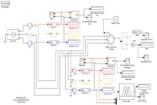
Fig. 12. Simulink block stator voltage conditions at 3 phase induction motor
Fig. 9. The graph of current results monitoring of load motor with 1.0 A current by simulating voltage imbalances
φ ⊂ (U ∏5 -Q E
SP os

—•—Tegangan
—•— Arus
Load Combination(W)
Fig. 10. The percentage graph imbalances of voltage and current in monitoring of load motor with 1.0 A current by simulating voltage imbalances.
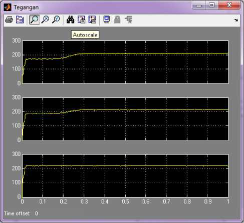
Fig. 13. Simulink results voltage per phase of the motor is loaded by simulating voltage imbalances
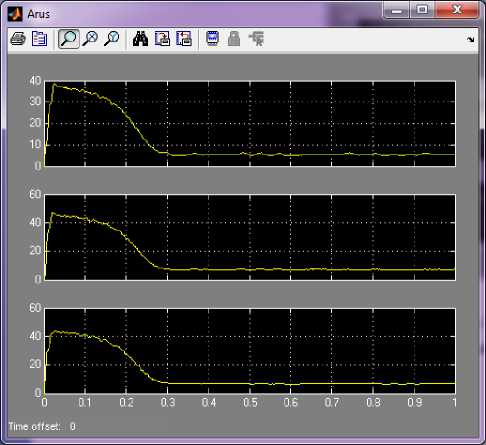
Fig. 14. Simulink results currents in each phase of the motor are loaded by simulating voltage imbalances
-
[7] Ballal, M.S. 2008. Fuzzy System for the Detection of Power Quality Performance on Induction Motor. India: Maharashtra Statet Electricity Transmission Co.Ltd.
-
[8] Standar Perusahaan Listrik Negara D5.004-1: 2012. Power Quality (Regulasi Harmonisa, Flicker Dan Ketidakseimbangan Tegangan).
In Simulink, load 1 and load 2 are set differently on different lines which is equivalent to a voltage imbalance of 12%. The difference in the amount of voltage and current in figure 13 and figure 14 is due to simulating motor imbalances and loads.
Designing a monitoring system for 3 phase induction motor condition using fuzzy logic method with 3 (three) phase voltage motor supply as input can be made and can be simulated properly.
Acknowledgment
The author gratefully acknowledge the financial support for this study by the Directorate General of Higher Education (Directorate of Higher Education), University of Udayana with 2018 national competitive funding for group research.
References
-
[1] Sinaga, Ronald P., “Pengaruh Tegangan Tidak Seimbang Terhadap Torsi Start-Torsi Maksimum Motor Induksi Tiga Phasa Starting Langsung”. Universitas Sumatra Utara, 2011.
-
[2] Dahono, P. A., "A very large ratio dc-dc power converter.", 2011: 36-36.
-
[3] Zeraoulia, M., “A Simple Fuzzy Logic Approach for Induction Motors Stator Condition Monitoring”. France: University of Western Brittany Rue de Kergoat, 2005.
-
[4] Mirabbasi, Davar. Effect of Unbalanced Voltage on Operation of
Induction Motors and Its Detection. Ahvaz, Iran : Shahid Chamran University.
-
[5] Wildi, Theodore. 2002. Elektrical Machines, Driver, and Power System Fifth Edition. Penerbit: Prentice Hall.
-
[6] Kusumadewi, S. 2004. Aplikasi Logika Fuzzy Untuk Pendukung Keputusan. Yogyakarta : Graha Ilmu.
Discussion and feedback