Remote Control Switching System Based on Wireless Technology
on
Journal of Electrical, Electronics and Informatics, p-ISSN: 2549–8304 e-ISSN: 2622–0393
52
Remote Control Switching System Based on Wireless Technology
Luh Kadek Pracanthi Dyah Sekartaji1, Nyoman Pramaita2, Nyoman Gunantara3
-
1 Department of Electrical Engineering, Faculty of Engineering, Udayana University Bali, Indonesia
Email: dyahsekartaji96@gmail.com
-
2 , 3 Telecommunication Systems Lab., Department of Electrical Engineering Faculty of Engineering, Udayana University
Bali, Indonesia
Email: 2 n_pramaita@yahoo.com, 3nyomangunantara@gmail.com
Abstract – Remote control switching system is used to control the switching of the electrical and electronic appliances from a distance. This remote serves to facilitate the use of the switching of electrical, and electronic appliances for people with disabilities, and the elderly. This paper develops a remote control system using radio frequency technology utilizing the principle of wireless system. The remote control system is constructed by RF433 module as the transmitter, and receiver, IC HT12E module as the encoder, and IC HT12D module as the decoder. To achieve the aim of this research: a transmitter system is designed to transmit a signal when the keypad is pressed; a receiver system is designed to receive the signal from the transmitter system, then the system will turn on and turn off the loads. Based on experimental results, this design system is capable to turn on and turn off the loads with a transmission distance up to 18 meters, without obstruction, and 15 meters with obstruction.
Index Terms — IC HT12E, IC HT12D, RF Transmitter, RF Receiver, Wireless
-
I. INTRODUCTION
Most houses are used the switching to turn on and turn off the electrical and electronics appliances manually. The manual switching makes some people, especially people with disabilities, and the elderly feel uncomfortable to control the home appliances, such as the lighting bulbs, air conditioners, fans, televisions, and so on.
For people with disabilities, and the elderly who live in the terrace house, or in the Balinese traditional house which has many building in their house compound will make their work to control the switching of the appliances more difficult. To facilitate their work, the easier method of switching is developed to replace the manual switching method into the advanced switching method for the electrical and electronic appliances by using a wireless remote control.
The development of the wireless remote control is progressing rapidly by utilizing a variety of technologies, such as radio frequency, infrared, and Bluetooth. Radio frequency remote control is used to control the distance objects by using various frequency signal that transmitted by the remote control devices. Radio frequency remote control has many advantages: it can be operated the switching without affected by the line of sight, transmits signal with a wider range than
Bluetooth technology, and is not sensitive to light, like infrared technology.
-
II. LITERATURE REVIEW
-
2.1 Amplitude Shift Keying Modulation
-
In the context of digital communication, Amplitude Shift Keying (ASK) modulation is a form of modulation that represents digital data as variations in the amplitude of carrier wave. The amplitude of an analog carrier signal varies in accordance with a bit stream where the frequency and phase are keeping constant [1]. Figure 1 illustrates a binary ASK signal (lower), together with the binary sequence which initiated it (upper).

Figure 1. The Message Signal and an ASK Signal
In ASK modulation, the level of amplitude can be used to represent binary logic 1’s and 0’s. The logic 1 is represented by the status ON (there is a carrier wave), while the logic 0 is represented by the status OFF (no carrier wave).
-
2.2 Radio Frequency module
Radio Frequency (RF) module is a component that can detect electromagnetic wave signals that are used by the communication system to send information through the air from one point to other points that propagate between the transmitting antenna, and receiving antenna. RF modules can be shown in Figure 2.

Figure 2. RF module
RF module has two electronic devices to send electromagnetic wave signals on the transmitter device and to receive electromagnetic wave signals on the receiver device. The RF Transmitter receives serial data and transmits wirelessly through the antenna with a transmission distance of 1 km. The data sent will be received by the RF Receiver which operates at the same frequency as RF Transmitter which is 433 MHz. The frequency used in the sending and receiving process must be the same, so there is no failure in the communication process [2].
-
2.3 IC HT12E module
IC HT12E is one of the encoders that is capable of encoding information that consists of N address bits and 12 N data bits. IC HT12E is often used as an encoder on the remote
control system. This IC has an address of 28 which allows
controlling more than one equipment. The IC HT12E module
can be shown in Figure 3.
Figure 3. IC HT12E module
IC HT12E begins a 4 data words transmission cycle upon receipt of a transmission enable (TE). This cycle will repeat itself as long as the transmission enable (TE) is held low. Once the transmission enable (TE) is high, the encoder output will complete its final cycle and stops [3].
-
2.4 IC HT12D module
IC HT12D is paired with IC HT12E. IC HT12D is capable of decoding information that consists of N address bits, and 12 N data bits. The IC HT12D module can be shown
in Figure 4.
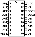
Figure 4. IC HT12D module
At first, IC HT12D will be in standby mode for a long time, if the oscillator is deactivated. A signal on the DIN pin activates the oscillator which in turn decodes the incoming data and address. IC HT12D will check the received address three times continuously. If the received address codes match the contents of the decoder’s address, the 12 N data bits are decoded to active the output pins, and the VT pin is set high to indicate a valid transmission. It will be last, unless the address code is incorrect or no signal is received [4].
-
III. METHODS
-
4.1 Modeling of RF Remote Control Switching System
-
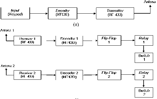
RF remote control switching system consists of two parts that are the transmitter device, and the receiver device. At the transmitter device consists of IC HT12E and RF Transmitter as modulator as well as transmitting ASK signals with a frequency of 433 MHz. Meanwhile, the receiver device consists of IC HT12D and RF Receiver as demodulator as well as receiving ASK signals with the frequency of 433 MHz. The modeling of the RF remote control switching system is shown in Figure 5.
(b)
Figure 5. Block diagram of RF Remote Control Switching System: (a) Transmitter Device, (b) Receiver Device
-
4.2 Design of RF Remote Control System
-
1. Design of Transmitter Device
The remote control system on the transmitter device consists of RF433 Transmitter, IC HT12E, resistor, and push button. The schematic diagram of the transmitter device can be shown in Figure 6.
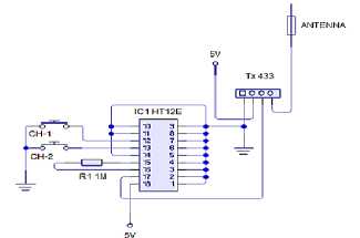
Figure 6. Schematic Diagram of Transmitter Device
If the push button on the keypad is pressed, the information will be encoded by the IC HT12E which contains 8 address bits, and 4 data bits. Each address bits or input data is set in one of the two logic condition (0 and 1). If the active condition is low, the IC HT12E will scan and transmit the condition from 12 address bits, and serial data. If the active condition is high, the IC HT12E is in standby condition. After the data is encoded by the IC HT12E, the data will be sent to the RF transmitter through pin 1 (ATAD pin). and will be digitally modulated by using the ASK modulation technique. The sent data from IC HT12E will be modulated in ASK and will be transmitted at the frequency of 433 MHz. Furthermore, the information will be transmitted through the transmitter antenna.
-
2. Design of Receiver Device
The remote control system on the receiver device consists of RF433 Receiver, IC HT12D, IC CD4017, BC558 transistor, BC547 transistor, resistors, capacitors, relay 5 V, and load. The schematic diagram of the receiver device can be
shown in Figure 7.
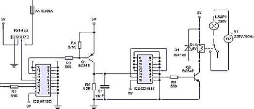
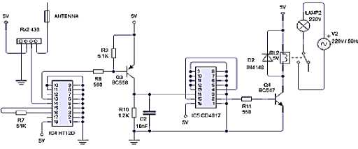
Figure 7. Schematic Diagram of Receiver Device
After the data is transmitted, the data will received by the receiver antenna and forwarded to the RF receiver. Then, the data will be processed by the RF receiver and will be demodulated to obtain digital data. The output data from the RF Receiver will be sent to the IC HT12D.
The decoder will check the received address three times continuously. If the information address bit isn’t the same as the contents of IC HT12D’s local address, then the output condition will remain the same as the previous output. If the information address bit code is the same as the contents of the IC HT12D’s local address, then the data bits will be decoded. The decoded information will process on the flip-flop, and the relay will turn on, and turn off the switching.
-
IV. RESULTS AND DISCUSSION
-
4.1 Testing of IC HT12E
-
Before testing the RF433 module, it is necessary to test the IC HT12E. This test is done to avoid any errors in the process of sending data. IC HT12E will be tested by giving the inputs to the AD12 pin, and AD13. The DOUT pin on the IC HT12E can be viewed from the addressing bits by using an oscilloscope. The measurement results of the IC HT12E testing can be shown in Figure 8 and Figure 9.
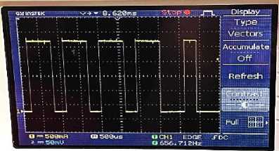
Figure 8. The Measurements Result of IC HT12E When Loads on the Channel 1 is turn on
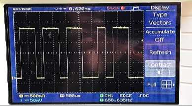
Figure 9. The Measurement Results of IC HT12E When Loads on Channel 2 is turn on
Based on Figure 8, and Figure 9, the input conditions that are given to the keypad with the output of IC HT12E are compatible. So it can be concluded that IC HT12E is working properly.
-
4.2 Testing of IC HT12D
The testing of IC HT12D will be measured by giving the input data to the pin AD12 and AD13 on the IC HT12E. Then, the addressing bits in the HT12D will be reviewed by using an oscilloscope. The measurement results of IC HT12D can be shown in Figure 10 and Figure 11.
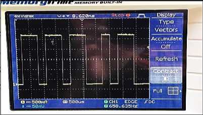
Figure 10. The Measurement Results of IC HT12D When Loads on Channel 1 is turn on
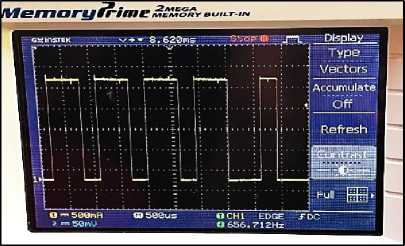
Figure 11. The Measurement Results of IC HT12D When Loads on Channel 2 is turn on
Based on Figure 10 and Figure 11, the resulting test of IC HT12E on channel 1 and channel 2 are compatible with the test result of IC HT12E shown in Figure 7 and Figure 8. Based on the test result, the IC HT12D is working properly with the expected and has the accuracy of receiving data at 100%. This indicates that the addressing bits that are sent by IC HT12E can be received by IC HT12D.
-
4.3 Testing of RF433 Module
The testing of the RF433 module can be measured by using a spectrum analyzer to determine the received signal power levels. Based on the experimental, the measurement results of the RF 433 module can be shown in Figure 12.
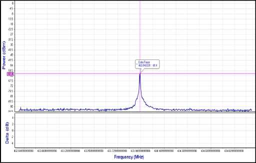
Figure 12. The Measurement Results of the Spectrum in RF433 Module
Based on Figure 12, it is known that the RF433 module generates the received signal power level of -61.4 dBm. To determine the received signal power level in milliwatts (mW), it can be calculated by using Equation 1:
Based on Equation 1, the power conversion from P(dBm) to P(mW) can be calculated:
= 7,24 × 10⁻⁷ mW
-
4.4 Testing of the Whole System
The testing of the whole system is carried out after the testing on each block has been done. Based on the experimental, the testing results can be shown in Table 1.
TABLE 1
MEASUREMENT RESULTS OF THE WHOLE SYSTEM
|
IC HT12E |
IC HT12D |
Load Conditions | |||
|
Data |
Address |
Data |
Address |
Load 1 |
Load 2 |
|
00 |
001001 |
00 |
001001 |
OFF |
OFF |
|
01 |
001011 |
01 |
001011 |
OFF |
ON |
|
10 |
011001 |
10 |
011001 |
ON |
OFF |
|
11 |
011011 |
11 |
011011 |
ON |
ON |
Table 1 is the measurement results of the whole system that obtained by observing pulse waveforms on the IC HT12E and IC HT12D on the oscilloscope. This testing is done by varying the data bits and addressing bits where the values of the two bits in the IC HT12E and IC HT12D are the same. Based on the measurement results in Table 1, it can prove that if the data bits and addressing bits on the IC HT12E are the same as the IC HT12D, so the communication device can occurr. It happens because the IC HT12D can detect the addressing bits that correspond to the IC HT12E’s addressing bits so that the load will receive the voltage.
-
4.5 Testing of Transmission Distance
The testing of transmission distance will be tested by using various distance variables to determine the performance of the system in the process of data transmission.
-
1. Testing of Transmission Distance in the LOS Conditions
This measurement was conducted to determine the maximum distance between the transmitter device and the receiver device in the LOS conditions. Based on the test, the measurement results of the transmission distance in the LOS condition are listed in Table 2.
TABLE 2
MEASUREMENT RESULTS OF TRANSMISSION DISTANCE IN THE
LOS CONDITION
|
Distance (m) |
Load 1 |
Load 2 |
|
3 |
ON |
ON |
|
5 |
ON |
ON |
|
7 |
ON |
ON |
|
9 |
ON |
ON |
|
11 |
ON |
ON |
|
13 |
ON |
ON |
|
15 |
ON |
ON |
|
18 |
ON |
ON |
|
21 |
OFF |
OFF |
The loads that are turned on indicates that the data sent from the transmitter is received properly. If the loads don’t turn on when the transmitter gives a command, then the receiver can’t receive the transmitted data by the transmitter. Based on Table 2, it is known that the load on channel 1 and channel 2 will turn on when the transmission distance between the transmitter and receiver up to 18 meters. The maximum transmission distance obtained from the measurement results
is different from the transmission distance in the theory. The theory said that the RF433 module is capable of transmitted signals up to 1 km. The difference is due to the antennas that are used in this research are not in accordance with the specifications of the system.
-
2. Testing of Transmission Distance in the NLOS Condition This measurement was conducted to determine the maximum distance between the transmitter device and the receiver device in the NLOS conditions. Based on the test, the measurement results of the transmission distance in the NLOS condition are listed in Table 3.
TABLE 3
MEASUREMENT RESULTS OF TRANSMISSION DISTANCE IN THE
NLOS CONDITION
|
Distance (m) |
Load 1 |
Load 2 |
|
3 |
ON |
ON |
|
5 |
ON |
ON |
|
7 |
ON |
ON |
|
9 |
ON |
ON |
|
11 |
ON |
ON |
|
13 |
ON |
ON |
|
15 |
ON |
ON |
|
18 |
OFF |
OFF |
The loads that are turned on indicates that the data sent from the transmitter is received properly. If the loads don’t turn on when the transmitter gives a command, then the receiver can’t receive the transmitted data by the transmitter. Based on Table 3, it is known that the load on channel 1 and channel 2 will turn on when the transmission distance between the transmitter and receiver up to 15 meters. The maximum transmission distance obtained from the measurement results is different from the transmission distance in the theory. The theoty said that the RF433 module is capable of transmitted signals up to 1 km. The difference is due to the antennas that are used in this research are not in accordance with the specifications of the system.
Based on Table 2 and Table 3, the transmission distances that can reach in the LOS condition are greater than the NLOS condition. This primary causes are signal attenuation due to penetration losses through walls, floors, and multipath propagation.
-
4.6 Testing of Received Signal Power Level
The testing of received signal power will be tested with various transmission distance variables to determine the received signal power in the system.
-
1. Testing of Received Signal Power Level in the LOS Condition
This measurement is done to determine the received signal power during the condition without any obstructions.
Based on the test, the measurement results of the received signal power are listed in Table 4.
TABLE 4 MEASUREMENT RESULTS OF RECEIVED SIGNAL POWER IN THE LOS CONDITION
|
Distance (m) |
Load 1 |
Load 2 | ||
|
Pr (dBm) |
Pr (mW) |
Pr (dBm) |
Pr (mW) | |
|
3 |
-51.12 |
7.72 × 10⁻⁶ |
-51.42 |
7.72 × 10⁻⁶ |
|
5 |
-51.97 |
6.32 × 10⁻⁶ |
-51.98 |
6.33 × 10⁻⁶ |
|
7 |
-51.97 |
6.32 × 10⁻⁶ |
-51.98 |
6.33 × 10⁻⁶ |
|
9 |
-54.46 |
3.58 × 10⁻⁶ |
-54.50 |
3.63 × 10⁻⁶ |
|
11 |
-57.54 |
1.76 × 10⁻⁶ |
-57.60 |
1.74 × 10⁻⁶ |
|
13 |
-59.74 |
1.06 × 10⁻⁶ |
-59.79 |
1.05 × 10⁻⁶ |
|
15 |
-60.12 |
9.73 × 10⁻⁷ |
-60.20 |
9.55 × 10⁻⁷ |
|
18 |
-62.59 |
5.51 × 10⁻⁷ |
-62.68 |
5.52 × 10⁻⁷ |
Table 4 is the measurement results of received signal power in LOS conditions which have dBm units and mW units. To determine the received signal power level in milliwatts (mW), it can be calculated by using Equation 1.
Based on Table 4, it is known that the received signal power is inversely proportional to the distance between the transmitter and receiver, so that the farther the distance between the transmitter and receiver, the received signal power will be smaller.
-
2. Testing of Received Signal Power Level in NLOS Condition
This measurement is done to determine the received signal power during the condition with obstructions. Based on the test, the measurement results of the received signal power are listed in Table 5.
TABLE 5
MEASUREMENT RESULTS OF RECEIVED SIGNAL POWER IN LOS CONDITION
|
Distance (m) |
Load 1 |
Load 2 | ||
|
Pr (dBm) |
Pr (mW) |
Pr (dBm) |
Pr (dBm) | |
|
3 |
-51.97 |
7.72 × 10⁻⁶ |
-51.98 |
6.33 × 10⁻⁶ |
|
5 |
-51.97 |
6.32 × 10⁻⁶ |
-51.98 |
6.33 × 10⁻⁶ |
|
7 |
-61.56 |
6.98 × 10⁻⁷ |
-61.78 |
6.64 × 10⁻⁷ |
|
9 |
-62.44 |
5.70 × 10⁻⁷ |
-62.84 |
5.20 × 10⁻⁷ |
|
11 |
-67.22 |
1.90 × 10⁻⁷ |
-67.40 |
1.82 × 10⁻⁷ |
|
13 |
-67.60 |
1.73 × 10⁻⁷ |
-67.92 |
1.61 × 10⁻⁷ |
|
15 |
-69.17 |
1.21 × 10⁻⁷ |
-69.35 |
1.16 × 10⁻⁷ |
Table 5 is the measurement results of received signal power in NLOS conditions which have dBm units and mW units. To determine the received signal power level in milliwatts (mW), it can be calculated by using Equation 1.
Based on Table 5, the received signal power is inversely proportional to the distance between the transmitter and receiver so that the farther the distance between the transmitter and receiver, the received signal power will be smaller.
Based on Table 4 and Table 5, it is known that the received signal powers in the LOS condition are smaller than in the NLOS conditions. This primary causes are signal attenuation due to penetration losses through walls, floors, and multipath propagation.
-
V. CONCLUSION
The remote for controlling the switching is capable to turn on and turn off the loads with the transmission distance up to 18 meters in the LOS condition, and 15 meters in the NLOS condition. The primary cause of the difference between the distance them is signal attenuation due to penetration losses through the walls, floors, and multipath propagation. Based on the results of this research, it can be also concluded that the performance of the system is not affected by the number of receivers that are used in the system. This because the quality of the system performance is determined by several factors, that are the distance of each receiver is still within the range of the transmitter, line of sight is still fulfilled, and depends on whether or not there is an obstruction during the process of signal transmission.
References
-
[1] Purkayastha, B.B & Sarma, K.K. 2015. A Digital Phase Locked Loop based Signal and Symbol Recovery System for Wireless Channel. India: Springer
-
[2] Astria, A. 2014. Pencari Kunci Wireless Menggunakan Sensor Radio Frekuensi (skripsi). Palembang: Politeknik Negeri Sriwijaya.
-
[3] Holtek Semiconductor, Inc. 2000. HT12A/HT12E 212 Series of
Encoder
-
[4] Holtek Semiconductor, Inc. 2002. HT12D/HT12F 212 Series of
Decoder
-
[5] Josephine, M.M. 2017. Design and Construction of Remote Control Switching Device for household Appliance Application. Advances in Science, Technology and Engineering Systems, 2 (4) : 154 – 167
-
[6] Manikandan, J. 2016. Design and Evaluation of Wireless Home Automation System. 2016 IEEE 1st International Conference on Power Electronics, Intelligent Control and Energy Systems, 1 : 1– 5
-
[7] Maradani, S. R., et al. 2017. Wireless Channel Losses and Emperical Channel Models. IOSR Journal of Electronics and Communication Engineering, 12 (2): 1 – 11
-
[8] Pathak, S, et al. 2017. RF Based Wireless Multi Switch Power Control Using Microcontroller. International Journal For Research and Development in Technology, 7(6): 363 – 370
-
[9] Rajender C, et al. 2017. Electrical Appliances in Home Control through IR Remote. International Journal Of Innovative Research in Technology, 3(9): 16 – 19
-
[10] Sugiono, B. 2012. Implementasi Sistem Nirkabel Menggunakan TLP434 dan RLP434 Pada Sistem Pengaktif Perangkat Elektronik Menggunakan Suara. (skripsi). Semarang L Universitas Diponegoro.
Discussion and feedback