Study of Transformer Lifetime Due to Loading Process on 20 KV Distribution Line
on
Journal of Electrical, Electronics and Informatics, Vol. 2 No. 2, August 2018
25
Study of Transformer Lifetime Due to Loading Process on 20 KV Distribution Line
A.A.N. Amrita1, W.G. Ariastina2, and I.B.G. Manuaba3
-
1 Electrical Engeneering Departement, Faculty of Engeneering
Udayana University (UNUD)
Badung, Bali, Indonesia ngr_amrita@unud.ac.id, 2Electrical Engeneering Departement, Faculty of Engeneering
Udayana University (UNUD)
Badung, Bali, Indonesia
w.ariastina@unud.ac.id, 3 Electrical Engeneering Departement, Faculty of Engeneering Udayana University (UNUD)
Badung, Bali, Indonesia
Abstract Power transformer is very important in electric power system due to its function to raise or lower the voltage according to its designation. On the power side, the power transformer serves to raise voltage to be transmitted to the transmission line. On the transmission side, the power transformer serves to distribute the voltage between the main substations or down to the distribution voltage. On the distribution side, the stresses are channeled to large customers or lowered to serve small and medium customers. As the power transformer is so importance, it is necessary to protect against disturbance, as well as routine and periodic maintenance, so that the power transformer can operate in accordance with the planned time. Some factors that affect the duration of the power transformer is the ambient temperature, transformer oil temperature, and the pattern of load. Load that exceeds the maximum efficiency of the transformer which is 80% of its capacity will cause an increase in transformer oil temperature. Transformer oil, other than as a cooling medium also serves as an insulator. Increasing the temperature of transformer oil will affect its ability as an isolator that is to isolate the parts that are held in the transformer, such as iron core and the coils. If this is prolonged and not handled properly, it will lead to failure / breakdown of insulation resulting in short circuit between parts so that the power transformer will be damaged. PLN data indicates that the power transformer is still burdened exceeding maximum efficiency especially operating in the work area of PLN South Bali Area. The results of this study, on distribution transformers with different loads, in DS 137, DS 263 and DS 363, show that DS 363 transformer with loading above 80% has the shortest residual life time compared to DS 263 and DS 137 which loading less than 80%.
Index Terms— Current, Voltage, Duration of Time, Distribution Transformer.
-
I. INTRODUCTION1
Power transformer is used to transform power. In power plant, this is used to increase power transferred to transmission line. In transmission line, however, this is used to transfer power between substations. In the distribution side, power is distributed to main customers or reduced to become low power to serve middle-level or low-level customer. As power transformer is so importance, it is highly required to protect and maintain it, therefore, their lifetime can be extended.
There are factors to influence lifetime of power transformer: ambient temperature, transformer’s oil temperature, and loading pattern. Loading process in distribution transformer influences voltage and current in transformer’s coil. In ideal condition, transformer is loaded up to 80% of its capacity due to its efficiency and losses. Power transformer management is related to the routine maintenance, for preventive, corrective, or detective. Shorten lifetime or damaged transformer caused by isolation fail in parts of transformer such as iron core and coils. This can happen due to the function of isolation to break parts with voltage to avoid flash over or spark over. Isolation fail can be caused by some factors, such as time, reduced-
dielectric strength, extra voltage and high current. Extra voltage in isolator, is a stress that must be counter by isolator for not being fail when isolating current. Inside isolation, electrons hardly link to their molecule, where this link forces stress caused by voltage. If this link is broken, isolation is disappeared, and it is fulfilled with power, there are moving electrons from one molecule to the others, where therefore, leaked current is created. On the other hand, High voltage that constantly flows inside coils cause temperature escalation.
PLN Area Bali Selatan says that in 2016, there are distribution transformers with load more than 80%, exceeds their capacity. Based on these facts, this research aims to analyze effect of loading to life time of power transformer by comparing power transformer with load of 50% - 60%, 70% - 80%, and 80% - 90% of its capacity. Results of this research can be used as a base of power transformer replacement or mutation, therefore power transformer damage that influences service continuity can be minimized.
There are previous studies related to power transformer lifetime and its load factor:
-
1. Janny Olny Wuwung, 2010. Here, effect of loading process to temperature increment in oil-submerged transformer is studied. Results of this study show that increment of loading factor raises aging factor that decrease the lifetime of a transformer.
-
2. Syafriyudin, 2011. In this study, transformer time of use prediction is calculated from daily voltage and current. Results of this study is that time of use of a transformer is reduced 8 months out of its normal time.
-
3. Sofyan and Afryastuti Herawati, 2015, studied effect of, loading process to efficiency and lifetime of transformer based on IEC 60076-7. Results of their research show that the highest efficiency of 96.66% occurs in peak load.
-
4. Winarso, 2014. Time of use of a transformer is predicted from daily voltage and current calculation. Results of this paper shows that for transformer with 5 years lifetime, it can be used for only 4 years and 7 months.
Transformer is a robust magnetoelectric tool used to change voltage. In general, Transformer composed by core formed by iron plate and two coils, primary and secondary coil. Ratio of voltage change depends ratio of those two coils (Abdul Kadir). Turn ratio of transformer is a deciding factor of the transformer type. If the turn ratio is lower than one, it is a step-up transformer. Otherwise, turn ratio that is higher than one means that the transformer is a step down one (Sumanto).
Distribution transformer used to distribute power to customers. A proper election of distribution transformer capacity is highly decided by the supplied load; therefore, it
can support the continuity of service, reliability, and transformer lifetime. Distribution transformer reach maximum efficiency when it is loaded until 80 percent of its capacity. When the load is too high, it is required to change the transformer, to insert new transformer, or to shift transformer (low-loaded transformer is shifted to serve high-loaded transformer or vice versa). Equation 1 is used to calculate distribution transformer rating where pf is power factor (cos phi = 0.85).
Distribution transformer rating (KVA) = Load (KW)/pf (1)
Prediction of Transformer lifetime can be analyzed through error value of transformer load. Error value of transformer is counted by using Equation 2.
P-P*
E =------x 100 % (2)
P
where :
E = Error value ( % )
P = Threshold value of transformer usage (80%)
P* = I ( % ) + V ( % ) + P ( % )
Meanwhile, each percentage value of I, V, and P can be calsulated by these methods:
Inom - Ibeban
Inom
V (%) = Vinput- Voulput x 100 (%)(4)
Pnomi-Pbeban P (%) =---------------x 100 (%)
Pnom
S
3V
Where :
S = Pnom = Power of power transformer ( KVA )
Inom = Phase current (A)
V = Vinput = Phase voltage ( V )
Voutput = VL = Load voltage from experiment ( V )
Ibeban = IL = Current from experiment ( A )
Pbeban = Load power ( KW )
Load power is calculated by using equation 7.
Pbeban = 3VVJc cos φ (7)
If load current IL is current that transfers power to load in a balance mode, therefore, in the curent power transmission with unbalance mode, value of load current can be stated with a, b, and c coefficients as it are shown in equation 8 where IR, IS, dan IT are load current in each phase, R, S, and T.
[Ir ] = a [ I ]
[Is ]= a [I ] (8)
[It ] = a [I ]
If power factors in these three phases is equal, even each current is different, transmitted power can be stated by equation 9.
Pbeban = (a + b + c) 3VLrJc cosΦ (9)
Due to the imbalanced load in each phase of secondary transformer, it is current to traverse the neutral of transformer, where this current causes losses. Losses value in the neutral of transformer can be calculated using equation 10. In this equation, PN is losses in the neutral conductor of transformer (Watt), IN is current arises in neutral conductor (Ampere), and RN is resistance in neutral conductor (Ohm)
2
PN = IN RN (10)
Afterwards, percentage of transformer lifetime is calculated through equation 11
Transformer lifetime (%) = 100(%) – E(%) (11)
If it is predicted that transformer can be used until 10 years, therefore its lifetime is calculated as folows.
Lifetime (day) is lifetime(%) multiply by 3600 days. Or it can be calculated by lifetime (year) which is lifetime(day) divide by 3600 days.
This research was conducted in three distribution transformers: DS 137 located in Tirta Nadi street, DS 263 in Danau Tamblingan street, and DS 363 which is located in Pulau Serangan street. These transformers are selected due to the early data from PT. PLN Bali South Regian in 2016., which is corresponding to the loading criteria of this research, 50% - 60%, 70% - 80%, and 80% - 90%. Data of each transformer is:
-
• DS 137 brand of B.D, installed in 2011, capacity of 250 KVA, 380/220 V, load of 47.91%.
-
• DS 263 brand of Unindo, installed in 2011, capacity of 250 KVA, 380/220 V, load of 71.37%.
-
• DS 363 brand of Trafindo, installed in 2011, capacity of 250 KVA, 380/220 V, load of 83.24%.
Measurement was conducted from 19.00 until 20.00, which is time of peak load. This schedule was repeated for seven days. The tool used is Clamp Power Meter.
Results of our research are shown in Table 1, 2, and 3, for DS 137, DS 263, and DS 363 respectively.
Table 1
Measurement results of DS 137
|
Day |
MEASUREMENT RESULTS | |||||||||
|
CURRENT (AMPERE) |
VOLTAGE ( VOLT ) | |||||||||
|
PHASE |
NEUTRAL PHASE | |||||||||
|
IR |
IS |
IT |
IN |
RS |
RT |
ST |
RN |
SN |
TN | |
|
1 |
163 |
178 |
185 |
57 |
391 |
401 |
398 |
227 |
225 |
231 |
|
2 |
184 |
193 |
205 |
47 |
391 |
400 |
397 |
227 |
225 |
229 |
|
3 |
114 |
124 |
223 |
95 |
398 |
390 |
400 |
223 |
231 |
227 |
|
4 |
98 |
67 |
81 |
37 |
403 |
397 |
409 |
228 |
235 |
231 |
|
5 |
193 |
151 |
163 |
58 |
387 |
398 |
395 |
225 |
223 |
229 |
|
6 |
193 |
151 |
163 |
58 |
387 |
398 |
395 |
225 |
223 |
229 |
|
7 |
123 |
48 |
122 |
80 |
394 |
387 |
401 |
223 |
230 |
226 |
|
Total |
1068 |
912 |
1142 |
432 |
2751 |
2771 |
2795 |
1578 |
1592 |
1602 |
|
Average |
152.57 |
130.29 |
163.14 |
61.714 |
393 |
395.86 |
399.29 |
225.43 |
227.43 |
228.86 |
Table 2
Measurement results of DS 263
|
DAY |
MEASUREMENT RESULTS | |||||||||
|
CURRENT (AMPERE) |
VOLTAGE ( VOLT ) | |||||||||
|
PHASE |
NEUTRAL PHASE | |||||||||
|
IR |
IS |
IT |
IN |
RS |
RT |
ST |
RN |
SN |
TN | |
|
1 |
282 |
265 |
251 |
46 |
385 |
397 |
392 |
223 |
221 |
227 |
|
2 |
196 |
246 |
260 |
90 |
383 |
394 |
391 |
223 |
220 |
225 |
|
3 |
199 |
216 |
269 |
91 |
395 |
387 |
397 |
224 |
226 |
225 |
|
4 |
324 |
257 |
186 |
143 |
389 |
403 |
398 |
227 |
225 |
230 |
|
5 |
259 |
258 |
273 |
112 |
388 |
380 |
397 |
220 |
227 |
226 |
|
6 |
266 |
339 |
266 |
125 |
380 |
397 |
387 |
224 |
218 |
227 |
|
7 |
267 |
197 |
303 |
164 |
388 |
380 |
396 |
219 |
229 |
224 |
|
Total |
1793 |
1778 |
1808 |
771 |
2708 |
2738 |
2758 |
1560 |
1566 |
1584 |
|
Average |
256.14 |
254.00 |
258.29 |
110.14 |
386.86 |
391.14 |
394.00 |
222.86 |
223.71 |
226.29 |
Table 3
Measurement results of DS 363
|
DAY |
MEASUREMENT RESULTS | |||||||||
|
CURRENT (AMPERE) |
VOLTAGE ( VOLT ) | |||||||||
|
PHASE |
NEUTRAL PHASE | |||||||||
|
IR |
IS |
IT |
IN |
RS |
RT |
ST |
RN |
SN |
TN | |
|
1 |
323 |
301 |
284 |
134 |
402 |
397 |
405 |
224 |
233 |
231 |
|
2 |
300 |
362 |
318 |
103 |
391 |
387 |
397 |
223 |
227 |
224 |
|
3 |
253 |
339 |
375 |
158 |
399 |
404 |
401 |
232 |
228 |
232 |
|
4 |
291 |
370 |
306 |
123 |
396 |
390 |
398 |
225 |
226 |
228 |
|
5 |
300 |
318 |
384 |
135 |
391 |
383 |
396 |
222 |
228 |
223 |
|
6 |
389 |
296 |
401 |
130 |
390 |
398 |
395 |
228 |
224 |
227 |
|
7 |
375 |
378 |
308 |
174 |
395 |
392 |
401 |
224 |
230 |
228 |
|
Total |
2231 |
2364 |
2376 |
957 |
2764 |
2751 |
2793 |
1578 |
1596 |
1593 |
|
Average |
318.71 |
337.71 |
339.43 |
136.71 |
394.86 |
393 |
399.00 |
225.43 |
228 |
227.57 |
Results of lifetime calculation in each distribution transformer are shown in Table 4, 5, and 6, for DS 137, DS 263, and DS 363 respectively.
Table 4
DS 137 with 50% - 60% load
|
Pnominal, (250 KVA = 250000 VA) |
250,000.00 |
VA |
|
294,117.65 |
Watt | |
|
Power faktor |
0.85 | |
|
V input |
220.00 |
V/phase |
|
I nominal (eq. 6) |
379.69 |
A/phase |
|
I load |
148.67 |
A/phase |
|
Voutput |
227.24 |
V/phase |
|
Pload (eq. 7) |
49,677.50 |
Watt |
|
49.68 |
KW | |
|
Percentage value : | ||
|
I (%), eq. 3 |
60.84 |
% |
|
V (%), eq. 4 |
(3.29) |
% |
|
P (%), eq. 5 |
83.11 |
% |
|
P*, e1. 6 |
140.66 |
% |
|
Error, eq 1 |
(75.83) |
% |
|
Lifetime, eq 11 |
175.83 |
% |
|
Lifetime in day |
6,329.90 |
day |
|
Lifetime in year |
17.58 |
year |
Table 5. DS 263 with 70% - 80% load
|
Pnominal, (250 KVA = 250000 VA) |
250,000.00 |
VA |
|
294,117.65 |
Watt | |
|
Power faktor |
0.85 | |
|
V input |
220.00 |
V/phase |
|
I nominal (eq. 6) |
379.69 |
A/phase |
|
I load |
256.14 |
A/phase |
|
Voutput |
224.29 |
V/phase |
|
Pload (eq. 7) |
84,479.02 |
Watt |
|
84.48 |
KW | |
|
Percentage value : | ||
|
I (%), eq. 3 |
32.54 |
% |
|
V (%), eq. 4 |
(1.95) |
% |
|
P (%), eq. 5 |
71.28 |
% |
|
P*, e1. 6 |
101.87 |
% |
|
Error, eq 1 |
(27.33) |
% |
|
Lifetime, eq 11 |
127.33 |
% |
|
Lifetime in day |
4,584.03 |
day |
|
Lifetime in year |
12.73 |
year |
Table 6
DS 363 with 80% - 90% load
|
Pnominal, (250 KVA = 250000 VA) |
250,000.00 |
VA |
|
294,117.65 |
Watt | |
|
Power faktor |
0.85 | |
|
V input |
220.00 |
V/phase |
|
I nominal (eq. 6) |
379.69 |
A/phase |
|
I load |
331.95 |
A/phase |
|
Voutput |
227.00 |
V/phase |
|
Pload (eq. 7) |
110,806.87 |
Watt |
|
110.81 |
KW | |
|
Percentage value : | ||
|
I (%), eq. 3 |
12.57 |
% |
|
V (%), eq. 4 |
(3.18) |
% |
|
P (%), eq. 5 |
62.33 |
% |
|
P*, e1. 6 |
71.72 |
% |
|
Error, eq 1 |
10.36 |
% |
|
Lifetime, eq 11 |
89.64 |
% |
|
Lifetime in day |
3,227.21 |
day |
|
Lifetime in year |
8.96 |
year |
These calculation results show that the higher the given load, affects to the diminished of lifetime of distribution transformer. Finally, Figure 1 shows the relations between lifetime and loading factor of power transformer.
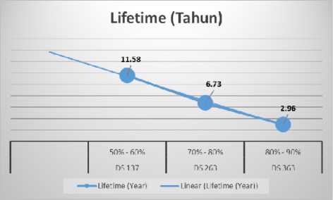
Fig. 1. Relation between loading factor and lifetime.
Loading in power transformer affects lifetime. The higher the load the shorter the lifetime. If it is assumed that power transformer can be used for 10 years, transformer DS 137 with brand of B.D then can be used for 11.58 years when it is loaded only 50% to 60% of its capacity. Meanwhile, DS 263 with brand of Unindo with load of 70% to 80% of its capacity, can be used for 6.73 years. Lastly, DS 363 with brand of Trafindo, where it is loaded with 80% to 90% of its capacity, its lifetime is only 2.96 years.
We would like to express our sincere gratitude to:
-
1. Rector of Udayana University, through Dean of Faculty of Engineering for the grant with value of 25.000.000 IDR, where therefore this research can be finished.
-
2. Head and secretary of the Electrical Engineering Department, students, colleges who have collaborated to finish this research.
References
-
[1] Abdul Kadir, 1989. Transformator. Penerbit PT. Elex Media Komputindo – Kelompok Gramedia, Jakarta
-
[2] Janny Olny Wuwung, (2010). Pengaruh Pembebanan terhadap Kenaikan Suhu pada Belitan Transformator Daya Jenis Terendam Minyak. Jurnal Tekno, Volume 07, No. 52, April 2010.
-
[3] Sumanto, 1991. Teori Transformator. Edisi Pertama, Cetakan Pertama. Penerbit Andi Offset, Yogjakarta. ISBN : 979–533–047-0.
-
[4] Syafriyudin, (2011). Perhitungan Lama Waktu Pakai Trasformator Jaringan 20 kV di APJ Yogjakarta. Jurnal Teknologi, Volume 4 Nomor 1, Juni 2011, 88-95.
-
[5] Sofyan, Afriyastuti Herawati, (2015). Pengaruh Pembebanan terhadap Effisiensi dan Usia Transformator (Studi Kasus Transformator IV Gardu Induk Sukamerindu Bengkulu) Berdasarkan Standar IEC 60076-7. Jurnal Amplifier, Vol. 5 No.2 Nopember 2015. ISSN : 2089-2020.
-
[6] Winarso, (2014). Estimasi Umur Pakai dan Rugi Daya Transformator. Jurnal Techno, ISSN 1410-8607, Volume 15, No. 2, Oktober 2014. Hal. 50-55.
Discussion and feedback