Graphic Monitoring on Test of Rocket Launch Payload
on
Journal of Electrical, Electronics and Informatics, Vol. 1 No. 2, September 2017
1
Graphic Monitoring on Test of Rocket Launch Payload
I N. Budiastra1*, C. G. I. Partha2, I G. N. Janardana3, and I W. A. Wijaya4
-
1,2,3,4 Department of Electrical Engineering,
Faculty of Engineering
Udayana University
Bali – Indonesia
Abstract Aviation technology and space is one of the leading technology for developed countries, especially in the form of rocket technology and charge. The countries that are capable of mastering these technologies will be respected by countries all over the world. Indonesia as the island nation with large and extensive maritime should have independence in the mastery of the technology of the rocket and payload. Therefore, continuous efforts are required to achieve independence, including through enhancing the sense of love of aviation technology and space technology, particularly at early stages the rocket and payload. Graphic Monitoring Test Rocket Launch Payload Attitude is the attitude of remote monitoring launch vehicle through the computer screen (display) continuously (real-time) data obtained from sensors-sensors that are mounted on the rocket's payload. 3D point (x, y, z) must be expressed as a graph visualization perspective drawings of rockets with the appropriate direction. The radar conducted computer GS (Ground Segment) or Ground Control Station (GCS. The result of the attitude of the Rocket Test launch Payloads have been able to communicate with the 3D data sending (x, y, and z) in real-time to the Ground segment. Wireless communication uses radio telemetry frequency 433 MHz, power of 100 mW, the distance range obtained in this study a maximum of 500 Meters in the air, without a hitch.
Index Terms— Graphic Monitoring, Payloads, Sensors.
Aviation and space technology is one of the leading technology for developed countries, especially in the field of rocket technology and charge. Countries that are capable of mastering these technologies will be respected by countries all over the world. Indonesia as the island nation and the State's large and extensive maritime already should have independence in mastering rocket technology and charge, therefore the required continuous efforts to achieve independence, only through the efforts of cultivate the sense of love of aviation technology and space technology, particularly at early stages of the rocket and payload.
In its development of a rocket payload forward the results of this architecture can be a forerunner of the birth of Indonesia satellite and rocket launcher works of Indonesia nation independently. While EDF rockets, especially the control technology, of course on a more sophisticated scale can be developed into the forerunner of Satellite Launcher Rocket. Besides Indonesian”s rocker community (KOMURINDO) also can increase the sense of unity about the importance of maintaining the dignity and sovereignty of the Indonesian aerospace through the mastery of aviation and space technology, especially rockets and cargo. In
addition, it can also shorten the distance difference of flight science and space technology and can expand its spread among universities across Indonesia Method
In this research, there are several stages that are done from the beginning of the study until the end of the study. The first stage is checked or check out the equipment used, the tools used must comply with the existing problems, namely can make a rocket payload (pay-load) Graphic Monitoring Test Rocket Launch Payload Attitude to find out directions from the plan of direction from the payload .
Other support tools also prepared i.e. by installing some software such as the Arduino IDE and application of ground station. The second piece of software that will be used to create programs that will run on sensor Accelerometer ADXL345, henceforth will be visualized in the form of graphs.
In the design of the hardware, will be made a series of vibration sensors that connect between the ADXL345 and Arduino and a USB cable that will connect the Arduino with the computer, as shown in Figure 1.
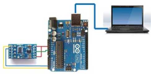
Fig.1. Design of accelerometer ADSL with Arduino and computer
Accelerometer ADXL345 and Arduino must be connected at some pins, Pin this pin that must be connected between the accelerometer ADXL345 and Arduino:
-
1) Pin CS (chip select) and a 5V pin on the Accelerometer ADXL345 connected with pins on an Arduino UNO 3v3. This pin serves as a place of power supply of both.
-
2) Ground (GND) Pin on the Accelerometer ADXL345 connected with GND pin on the Arduino. This pin serves as a place to ground.
-
3) Pin (SDA) on Accelerometer ADXL345 connected with A4 pin on the Arduino. This pin serves as the serial input data on I2C communication.
-
4) Pin (SCL) on Accelerometer ADXL345 connected with pin A5 on the Arduino UNO. SCL pin on the accelerometer ADXL345 here serves as a clock on the I2C data communications.
-
5) USB cable will be connected to the Notebook via the USB port found on the Arduino and accelerometer and the microcontroller automatically will be active once connected on the notebook marked with RX TX and lights turned on.
The Arduino IDE is useful of the Arduino software as the compiler for the Arduino microcontroller type using C language for programming. On the Arduino IDE software for this program will be created that contains instructions that will be executed by the Arduino microcontroller. Program that will be created will arrange communication between Arduino with Accelerometer ADXL345 using the I2C communication as well as setting work on the accelerometer ADXL345. In a program that made this microcontroller will only read the data axis acceleration x, y and z from the measurements performed by the accelerometer ADXL345 and further the acceleration results data will be sent to your computer. This is done by way of making the microcontroller just read the output to address acceleration axes x, y and z on the accelerometer ADXL345. The first step to do initialization of accelerometer ADXL345 and instruction-instruction used in the Arduino microcontroller
The design of data communication with no wired or wireless was conducted after the program can communicate with the Arduino and accelerometer response has been received in its entirety through the USB cable. The design is shown in Figure 2.
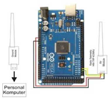
Fig. 2. The Arduino with radio communication
The selected communication radio is a radio that has a frequency that is legal and free to use. In this yg frequency planning used frequency is 433MHz, with a maximum transmitter power of 100mW.
In the operation of the rocket's payload uses the accelerometer ADXL345, common error sending data for axes x, y and z. ADXL345 Sensor will get data acceleration be the change of layout and positioning of the payload of the axis x, y and z. then the data is taken will be sent to the Arduino using the communication Inter Integrated Circuit (I2C). In the Arduino microcontroller is who has been using software inside deprogram compiler Arduino IDE 1.0.6 so that data shown data axes x, y and z. after the data processed on the Arduino UNO R3 and produced data on axes x, y and z then the data is sent to your computer by using the radio TX/RX 433MHz for further processed and displayed on the computer through the application of Visual Basic in the form of graphs and numeric data. The data obtained are then processed using the standard deviation equation for knowing the value of the frequency limit will be the reference values for indicators of error.
Real payload by using the accelerometer and gyroscope sensor which has been designed using software sketch up pro can be seen in Figure 3. The specifications of the rocket's payload shown in table 1. This specification refers to the basic rules of the dimensions of the payload that is issued by KOMURINDO/Competition in Indonesia.
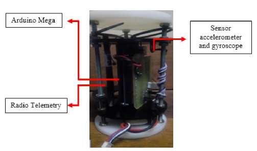
Fig 3.The Payload
TABLE I
Specifications Payloads
No. Specifications Payload
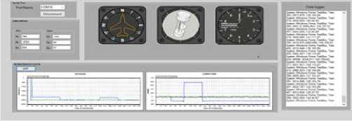
Fig. 4. Test results the Payload using the 3D view via GCS
In testing the test equipment charge rocket launcher equipment required to carry payloads into the air. Rocket launchers are usually used to belong to the LAPAN. In this study it is not possible in a rocket launcher to get to testingtesting a rocket payload in the making. To address those in the study is made of a tools lifter that uses rotary wing system commonly called also a vehicle without crew/drones. Spacecraft Launchers like shown in Figure 5.
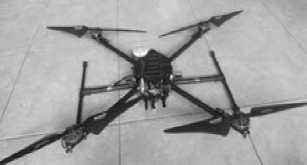
Fig. 5. The Spacecraft Launchers
10 cm
20 cm
10 cm
638 g
11.1 VDC2.2 A Arduino Mega 5 V
In the operation of the rocket's payload using the accelerometer and gyroscope an error occurred, it is often the fault of the shipping data for axes x, y and z. Sensor and gyroscope will take the form of acceleration data changes the location and position of the payload of the axis x, y and z. then data will be sent to the Arduino using the communication Inter Integrated Circuit (I2C). In the Arduino microcontroller is who has been using software inside deprogram compiler Arduino IDE 1.0.6 so that data shown data axes x, y and z. after the data processed on the Arduino and produced data on axes x, y and z, then the data is sent to your computer by using the radio TX/RX 433MHz for further processed and displayed on the computer through the application interface GCS in the form of graphs and numeric data. The data obtained are then processed using the standard deviation equation for knowing the value of the frequency limit will be the reference values for indicators of error.
To perform the test Graphics Monitoring research Rocket Launch Test Payload Attitude, then thoroughly done by carrying and fly a payload. In this design the payload has a weight of no more than 1000 grams with a diameter of 10 Cm and a height of 20 Cm. Prior to launch, testing is done on the ground to find out the function of radio telemetry payload and spacecraft telemetry radio the Launcher. While the process of launching the rocket test charge is shown in Figure 6. In the process of this launch was successful and the data from the payload can be send to the ground control station. Accelerometer data delivery that was in the payload sent in real time starting from a distance of 0 up to 500 meters. After passing over a distance of 100 meters, deliveries disrupted and disjointed. Radio telemetry data from the specifications used are of 100 mW, with a range as far as 1000 meters.
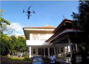
Fig. 6. The launch of the rocket's Payload
-
III. Conclusion
-
1) Payload is a charge by applying high-tech monitoring technology as having boundaries in accordance with sensor-sensor is used.
-
2) Payload rocket test can communicate with the Ground control system and transmit the data speed, the acceleration of the launch as well as the position of the charge.
-
3) The unmanned rides have been controlled by radio control for rocket load testing.
Acknowledgment
The author gratefully acknowledge the financial support for this study by the Directorate General of Higher Education (Directorate of Higher Education), University of Udayana with 2016 national competitive funding for fundamental research
References
-
[1] Anonymous. (t. yrs.). Analog Device. Taken back from ADXL345 Data Sheets: http://www.analog.com/static/imported-files/data sheets/ADXL345.pdf
-
[2] Anonymous. (t. yrs.) the Arduino. Taken back from the Arduino IDE: http://www.Arduino.cc/downloads/ArduinoIDE
-
[3] Anonymous. (t. yrs.) Atmel. Taken back from 328 Datasheet: ATMega Microcontroller www.atmel.com
-
[4] Arduino. (t. yrs.) Taken back from www. Arduino. cc: http://www.Arduino.cc/learn/arduino
-
[5] Hendry. 2009. Berbagai Aplikasi Database Dengan Visual Basic 6.0. Jakarta : Elexmedia Komputindo.
-
[6] Kuhnel, Claus. 2001. BASCOM Programming of Microcontrollers with Easy.USA: Universal Publishers
-
[7] LAPAN, (2016), Buku Panduan Perlombaan KOMURINDO 2016 Jakarta: Derektorat Jendral Pendidikan Tinggi.
-
[8] Pitowarno, Endra. 2014. Sosialisasi Komurindo 2015
Discussion and feedback